Modern aircraft are filled with digital systems — flight management computers, engine control units, digital avionics buses, and programmable data loaders — all of which store and transmit information as sequences of ones and zeros. To read fault codes, interpret data bus traffic, configure avionics line-replaceable units (LRUs), and make sense of maintenance documentation, an Aviation Maintenance Technician (AMT) must be comfortable working in both the binary (base-2) and hexadecimal (base-16) number systems. These are not abstract math exercises; they are daily tools for anyone maintaining fly-by-wire flight controls, ARINC 429 data buses, or aircraft computer systems.
This article builds a solid foundation — explaining how each system works, why they exist, and how to convert between them — with material grounded in the FAA General test knowledge areas covering mathematics and number systems.
The Decimal System as a Starting Point
Before tackling binary or hexadecimal, it helps to examine the familiar decimal (base-10) system. In base-10, each position in a number represents a power of ten: the rightmost column is 100 (ones), the next is 101 (tens), then 102 (hundreds), and so on. The digits available are 0 through 9. When you exhaust all digits in a column (reaching 9), you carry one into the next column and reset to 0. Every number system works the same way — the only differences are the base (the number of unique digits available) and the column weights (powers of that base).
Binary: The Language of Digital Logic
The binary number system uses a base of 2, meaning only two digits exist: 0 and 1. These correspond directly to the two stable states of an electronic switch or transistor — off (0) and on (1). Because semiconductor logic gates can reliably distinguish only two voltage states (low and high), binary is the native language of all digital electronics, including aircraft computers.
Each binary digit is called a bit (binary digit). A group of eight bits is a byte. A group of four bits is called a nibble. Column weights in binary are powers of 2, moving left from the rightmost position:
- Bit position 0 (rightmost): 20 = 1
- Bit position 1: 21 = 2
- Bit position 2: 22 = 4
- Bit position 3: 23 = 8
- Bit position 4: 24 = 16
- Bit position 5: 25 = 32
- Bit position 6: 26 = 64
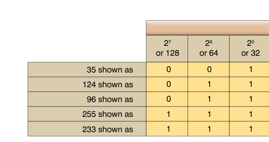
- Bit position 7 (leftmost of a byte): 27 = 128
Converting Binary to Decimal
To convert a binary number to decimal, multiply each bit by its column weight and sum the results. For example, take the binary number 10110101:
- 1 × 128 = 128
- 0 × 64 = 0
- 1 × 32 = 32
- 1 × 16 = 16
- 0 × 8 = 0
- 1 × 4 = 4
- 0 × 2 = 0
- 1 × 1 = 1
Sum: 128 + 32 + 16 + 4 + 1 = 181 in decimal. An AMT might encounter such a value in a fault word from an ARINC 429 data bus label or an engine control unit memory dump.
Converting Decimal to Binary
The standard method is repeated division by 2. Divide the decimal number by 2, record the remainder (0 or 1), then divide the quotient by 2 again, and repeat until the quotient is 0. Reading the remainders from bottom to top gives the binary result. For example, converting decimal 45:
- 45 ÷ 2 = 22 remainder 1
- 22 ÷ 2 = 11 remainder 0
- 11 ÷ 2 = 5 remainder 1
- 5 ÷ 2 = 2 remainder 1
- 2 ÷ 2 = 1 remainder 0
- 1 ÷ 2 = 0 remainder 1
Reading remainders bottom to top: 101101. Verify: 32 + 8 + 4 + 1 = 45. Correct.
Hexadecimal: The Technician's Shorthand
Binary is precise but cumbersome — an 8-bit byte requires eight individual digits to write. The hexadecimal (hex) system uses base 16, which makes it a natural and compact shorthand for binary data. With sixteen unique symbols, a single hex digit represents exactly four binary bits (one nibble), and two hex digits represent a full byte. This makes hex widely used in avionics fault codes, memory addresses, software version identifiers, and data bus word labeling.
Because base 16 requires sixteen digits and the decimal system only provides ten (0–9), six additional symbols are borrowed from the alphabet: A = 10, B = 11, C = 12, D = 13, E = 14, F = 15. Hex values are commonly prefixed with 0x (in software) or written with a subscript 16, for example 0x2F or 2F16.
Column weights in hexadecimal are powers of 16:
- Position 0 (rightmost): 160 = 1
- Position 1: 161 = 16
- Position 2: 162 = 256
- Position 3: 163 = 4,096
Converting Hexadecimal to Decimal
Multiply each hex digit by its column weight (as a decimal value) and sum. For example, convert 3B16 to decimal:
- 3 × 16 = 48
- B (11) × 1 = 11
Sum: 48 + 11 = 59 in decimal.
For a larger value, 1A416:
- 1 × 256 = 256
- A (10) × 16 = 160
- 4 × 1 = 4
Sum: 256 + 160 + 4 = 420 in decimal.
Converting Binary to Hexadecimal — The Key Skill
Because one hex digit equals exactly four bits, conversion between binary and hex is faster than going through decimal. Simply group the binary number into nibbles (groups of four bits) starting from the right, padding with leading zeros if necessary, then substitute the hex equivalent for each group.
Example: Convert binary 1011 1110 to hex:
- Left nibble: 1011 = 8 + 2 + 1 = 11 = B
- Right nibble: 1110 = 8 + 4 + 2 = 14 = E
Result: BE16. An AMT reading a two-byte fault code from a Central Maintenance Computer (CMC) printout could decode it instantly using this method.
Reversing the process is equally direct: replace each hex digit with its 4-bit binary group. C716 becomes 1100 0111 in binary — again, no intermediate decimal step required.
Why These Systems Matter in Avionics Maintenance
Understanding binary and hexadecimal is not merely academic. Practical applications encountered on the hangar floor and in maintenance documentation include:
- Fault code interpretation: Aircraft CMCs and Built-In Test Equipment (BITE) often display fault codes in hex. Misreading a hex fault code can send a technician troubleshooting the wrong LRU, wasting time and introducing errors.
- ARINC 429 data bus labels: ARINC 429, the dominant civil avionics data bus standard, uses 32-bit words. The 8-bit label field is conventionally documented and expressed in octal notation (as a three-digit octal value) in the ARINC 429 specification, though it is routinely discussed in binary and hex in avionics manuals and data bus analyzers.
- Software part numbers and checksums: Avionics software loads are verified using hex checksums. A technician loading a database update to a Flight Management System (FMS) confirms the hex checksum in the aircraft maintenance manual matches the loaded file to ensure data integrity.
- Bit-flag status words: Many avionics systems pack multiple on/off status flags into a single binary word. Knowing which bit position (bit 0 through bit 15, for instance) corresponds to which system condition requires direct binary interpretation.
- Memory addressing: When interfacing with avionics test equipment or performing a software reload, memory addresses are displayed in hexadecimal.
Key Numbers and Rules
- Binary (base-2) uses only 0 and 1; each digit is a bit.
- 8 bits = 1 byte; 4 bits = 1 nibble.
- Column weights in binary: 1, 2, 4, 8, 16, 32, 64, 128 (left to right = 20 through 27).
- Hexadecimal (base-16) uses digits 0–9 and A–F (A=10, B=11, C=12, D=13, E=14, F=15).
- One hex digit = exactly 4 binary bits (one nibble).
- Two hex digits = exactly 8 binary bits (one byte).
- Maximum value of one byte: binary 11111111 = hex FF = decimal 255.
- To convert binary → hex: group bits into nibbles of 4, substitute hex symbol for each group.
- To convert decimal → binary: divide repeatedly by 2, read remainders bottom to top.
- To convert hex → decimal: multiply each digit by its power-of-16 column weight and sum.
Common Test Traps
- Confusing the letter O with zero: In hex, the digit is always the number zero (0), never the letter O. In technical documentation they can look identical — read carefully and rely on context.
- Starting the nibble grouping from the wrong end: When converting binary to hex, always group from the right (least significant bit) side, padding the leftmost group with zeros if it has fewer than four bits. Grouping from the left produces a wrong answer.
- Forgetting that A–F represent values 10–15, not single-digit numbers: A common error is treating hex B as decimal 1 and 1 separately instead of 11. Each hex digit is a single symbol representing a value from 0 to 15.
- Skipping the column weight step in multi-digit hex conversions: Students sometimes add the digit values without multiplying by column weights — for example, treating 3B as 3 + 11 = 14 instead of (3 × 16) + 11 = 59. Always apply position weights.
- Confusing binary bit numbering conventions: Bit 0 is the least significant bit (rightmost) in standard generic binary notation, but some avionics documentation uses different conventions — for example, the ARINC 429 specification numbers bits 1 through 32 (not zero-indexed), with bit 1 as the least significant bit transmitted first. Check the specific document's convention before interpreting status words or fault bits.