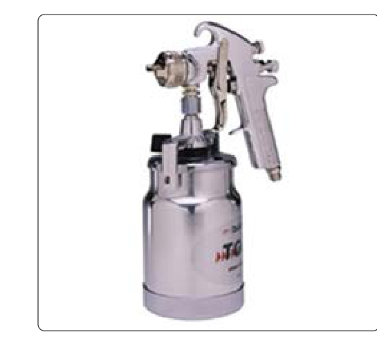
Applying a quality finish to an aircraft structure is far more than a cosmetic exercise — paint protects aluminum, steel, and composite surfaces from corrosion, moisture, UV degradation, and chemical attack. The spray gun is the central tool in that process, and how it is set up and adjusted directly determines whether the finished coat is smooth, uniform, and properly bonded, or riddled with runs, orange peel, dry spray, or solvent pops. For the Aviation Maintenance Technician (AMT) working on airframe finishes, mastering spray gun fundamentals is both an FAA knowledge-test requirement and a core practical skill.
This article covers the types of spray guns used in aircraft refinishing, the function of each major adjustment, how fluid, air, and fan pattern interact, and the technique adjustments that produce a professional result on aircraft surfaces. All guidance is grounded in FAA maintenance handbook principles.
Types of Spray Guns Used in Aircraft Finishing
Two broad categories of spray guns appear in aviation refinishing work:
- Conventional (air-atomizing) spray guns use a high volume of compressed air — typically 40–90 PSI at the gun — to atomize the liquid coating into a fine mist. They produce an excellent finish quality but generate considerable overspray and are less efficient in material transfer.
- HVLP (High Volume, Low Pressure) spray guns deliver a high volume of air at low atomizing pressure — generally 10 PSI or less at the air cap, a figure commonly referenced in industry and air-quality regulations. HVLP guns are now widely used because of their higher transfer efficiency, meaning less material is lost to overspray, and many modern aircraft refinishing operations use HVLP equipment exclusively.
Both types use the same fundamental three-control adjustment system, but the specific pressure settings differ significantly between them. The AMT must always consult the coating manufacturer's data sheet and the gun manufacturer's specifications when setting up for a particular material.
Major Components and Their Functions
Understanding each part of the spray gun is the foundation of proper adjustment:
- Air cap — the front of the gun where compressed air exits through a center orifice and side horns. The center orifice atomizes the fluid; the side horn air ports shape and control the fan pattern width. The air cap is matched to the fluid nozzle and needle for a specific viscosity range.
- Fluid nozzle (tip) — meters the coating material as it exits the gun. Nozzle orifice size is chosen based on material viscosity; heavier materials such as high-build primers require a larger orifice, while light sealers or topcoats may use a smaller orifice. The AMT should always follow the gun and coating manufacturer's recommended tip size rather than a fixed numeric range.
- Fluid needle — seats inside the fluid nozzle and is retracted by the trigger to allow material flow. The fluid needle adjustment screw on the rear of the gun limits how far the needle can retract, directly controlling the volume of material delivered per pass.
- Air valve — controls the volume of air delivered to the cap. On most guns it is interlocked with the trigger so that air flows slightly before the fluid needle opens, preventing material from dripping without atomization air.
- Fan control (pattern width) knob — adjusts the volume of air flowing to the side horn ports on the air cap, spreading or narrowing the elliptical fan pattern. The direction of rotation that widens or narrows the pattern varies by gun manufacturer and model, so the AMT should verify the specific gun's operating instructions rather than assume a universal direction.
- Fluid adjustment knob — limits needle retraction, thereby reducing or increasing the amount of material delivered. This knob is usually on the rear of the gun body.
- Air inlet and regulator — many gun handles incorporate a small gauge and adjustable regulator. The pressure at this point must be set to the gun manufacturer's specification for the material being sprayed.
The Three Core Adjustments
Every spray gun setup revolves around balancing three interdependent variables: air pressure, fluid flow, and fan pattern width. Changing one affects the others, which is why adjustments are always made methodically and tested on a spray-out card or scrap surface before application to the aircraft.
Air Pressure
Air pressure is set at the regulator supplying the gun, or at the gun-mounted regulator if present. The correct setting depends entirely on the gun type and the coating material. For a conventional gun spraying a medium-viscosity aerospace topcoat, 45–65 PSI at the gun inlet is a common range. For an HVLP gun, the inlet pressure may be 25–30 PSI to achieve the required 10 PSI or less at the air cap. Using too little pressure produces large, poorly atomized droplets that create an orange-peel or coarse texture. Using too much pressure causes excessive overspray, dry spray (droplets that partially cure before reaching the surface), and solvent evaporation that can result in poor film build and reduced gloss.
Fluid Flow
The fluid adjustment knob is backed out (counterclockwise) to open needle travel — this increases material delivery. The optimal setting delivers enough material to wet the surface thoroughly without flooding it. A common starting point is to open the fluid knob about two to two-and-a-half turns from fully closed, then adjust based on the spray-out test. Excess fluid flow combined with slow gun speed causes runs and sags. Insufficient fluid flow with fast gun speed leaves a thin, dry coat that may not achieve the required film thickness for corrosion protection.
Fan Pattern Width
The fan control knob adjusts how wide the elliptical spray pattern is. For broad, flat aircraft panels, a wide fan (fully open) is most efficient and minimizes lap marks. For narrow surfaces such as control surface edges, ribs, or stringers, reducing the fan width gives more control and reduces wasted material. A correct fan pattern should be an even, well-atomized ellipse with no heavy center band or heavy edges. A heavy center band indicates too little fan air; heavy edges (a bowtie or hourglass shape) indicate too much fan air relative to fluid delivery or a clogged center orifice.
Gun Distance and Speed
Even a perfectly adjusted gun will produce a poor finish if gun distance and travel speed are inconsistent. The recommended gun-to-surface distance for most aircraft refinishing applications is 6 to 10 inches for conventional guns and slightly closer — 6 to 8 inches — for HVLP guns. Holding the gun too far away increases overspray, causes dry spray, and reduces film build. Holding it too close floods the surface and causes runs. The gun should be moved parallel to the surface (not arced), and each pass should overlap the previous pass by approximately 50% to achieve a uniform film thickness.
Gun travel speed is also critical. There is no single fixed numeric speed that applies to every gun and material; the correct speed is ultimately determined by observing the wet film on the spray-out panel: the surface should wet out with a uniform sheen without runs forming.
Viscosity and Material Preparation
Before adjusting the gun, the coating material itself must be properly prepared. Most aerospace coatings require reduction (thinning) to a spray viscosity specified by the manufacturer, measured with a viscosity cup (commonly a Zahn or Ford cup). The correct viscosity ensures proper atomization at the intended air pressure. Using material that is too thick — even with a wide-open fluid knob — will produce poor atomization and orange peel. Material that is too thin will sag easily and may not provide the required film build for protection. Two-component coatings (such as epoxy primers and polyurethane topcoats common in aviation) must also be properly mixed at the manufacturer's specified ratio and allowed to induct (stand after mixing) for the recommended time before spraying.
Why Proper Setup Matters for Airworthiness
On an aircraft, a finish is not purely aesthetic. FAA maintenance standards recognize that the protective coating system is part of the corrosion prevention structure of the aircraft. An improperly applied finish — whether due to poor adhesion from incorrect surface prep, insufficient film thickness from a poorly adjusted gun, or contamination from excessive overspray — can allow moisture and contaminants to reach the substrate, initiating corrosion that can compromise structural integrity. The AMT is responsible for ensuring that finish work is done in accordance with the aircraft manufacturer's maintenance manual and, where applicable, approved data.
Key Numbers and Rules
- HVLP atomizing pressure: 10 PSI or less at the air cap (a widely used industry and air-quality regulatory standard, such as SCAQMD rules; also a common reference point in AMT training).
- Conventional gun inlet pressure: typically 45–65 PSI, consult gun and coating manufacturer specs.
- Gun-to-surface distance: 6–10 inches (conventional); 6–8 inches (HVLP).
- Overlap per pass: approximately 50% of the fan width.
- Fluid knob starting point: 2 to 2.5 turns open from fully closed, then adjust by spray-out test.
- Fan pattern test: spray a short burst on a piece of cardboard held vertically — the pattern should be an even ellipse with consistent density, no heavy center, no hourglass shape.
- Material reduction: always reduce to manufacturer-specified viscosity measured with a calibrated viscosity cup.
Common Test Traps
- Confusing HVLP pressure values with conventional values. Test questions may give a pressure and ask which gun type it describes. Remember: HVLP delivers high volume of air but at low pressure at the cap — 10 PSI or less — even though inlet pressure may be higher.
- Attributing orange peel to the wrong cause. Orange peel can result from air pressure too low (poor atomization), material too thick (high viscosity), gun too far from surface, or gun moving too fast. Do not assume it always means just one thing.
- Mixing up fluid knob and fan knob functions. The fluid knob controls material volume (needle retraction); the fan knob controls pattern width via side horn air. They are separate adjustments with separate effects.
- Ignoring induction time for two-component materials. Some test questions address spraying two-component coatings immediately after mixing versus allowing the required induction time. Skipping induction can result in poor film properties even with a perfectly adjusted gun.
- Gun arcing vs. parallel movement. Arcing the gun (pivoting from the wrist) changes the gun-to-surface distance through each stroke, producing a coat that is thick in the center and thin at the edges. The gun must be kept parallel to the surface throughout each pass.