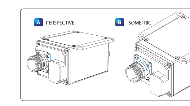
When an aircraft maintenance technician opens a technical manual or maintenance publication, the illustrations inside must communicate complex three-dimensional shapes quickly and without ambiguity. Two of the most important drawing types used for this purpose are isometric and oblique pictorial drawings. Unlike a standard orthographic projection, which breaks a part into separate front, top, and side views, pictorial drawings present a component as it appears in space — giving the reader an immediate intuitive sense of the object's overall form. Knowing how each type is constructed, what distortions it introduces, and when each is the preferred choice is fundamental knowledge for the FAA Aviation Maintenance Technician (AMT) General written test and for daily work on the shop floor.
Both isometric and oblique drawings belong to the broader family called pictorial drawings, which are also sometimes called 3D drawings in everyday shop language. They are not replacements for full orthographic multiview drawings when precise measurements are required, but they are invaluable companions — helping a technician visualize what a finished bracket, duct, or fitting should look like before or after fabrication.
Isometric Drawings
The word isometric comes from the Greek for "equal measure," and that equality is the defining characteristic of this drawing type. In an isometric drawing, the object is positioned so that its three primary axes — height, width, and depth — are all equally inclined to the picture plane. This results in each axis appearing at a specific, fixed angle.
Specifically, the two horizontal axes (width and depth) are drawn at 30 degrees above a horizontal reference line, one going to the upper left and one going to the upper right. The vertical axis (height) remains perfectly vertical. Together these three axes create a characteristic "Y" shape when you look at the corner of an isometric box. All lines parallel to one of these three axes are called isometric lines, and they are drawn to true scale — meaning you can measure directly along them with a ruler and get a meaningful dimension. Lines that are not parallel to the three principal axes are called non-isometric lines, and they are not drawn to true length; they must be located point-by-point from isometric coordinates.
Because all three axes are equally foreshortened at the same ratio, isometric drawings have a clean, balanced appearance and allow dimensions to be scaled along any of the three primary directions. This makes isometric drawings particularly useful when the technician or engineer needs to convey overall shape, assembly relationships, or approximate size in a single clear view. Isometric pictorials are common in aircraft maintenance manuals for exploded-view assembly diagrams, where parts are pulled apart along isometric axes to show how components nest together.
Circles and Curves in Isometric Views
One complication with isometric drawings is that circles do not appear as circles; they appear as ellipses. A circular hole or a round boss on a part must be carefully constructed as an approximate ellipse (often using a four-center ellipse construction method) to look correct. Technicians reading isometric drawings should recognize that any elliptical shape in the drawing likely represents a true circle on the actual part. Curved lines and arcs require similar point-by-point construction. Isometric ellipse templates are available to speed up drafting, but the underlying geometry is important to understand for interpreting drawings accurately.
Oblique Drawings
An oblique drawing takes a different approach to showing three dimensions on a flat surface. In an oblique drawing, one face of the object is drawn in its true shape directly on the picture plane — meaning it is drawn exactly as it would appear in a straight-on orthographic front view. From that true-shape front face, receding lines representing depth are projected backward at an angle, typically 45 degrees to the horizontal, although other angles are sometimes used.
This approach has an important advantage: any feature that lies on the front face — including circles, arcs, and irregular curves — is drawn in its true shape without distortion. This makes oblique drawings especially practical when the most complex or most feature-rich face of a part faces the viewer. For example, a plate with several drilled holes and a machined contour on its face is far easier to represent in oblique view than in isometric view, because the circles on the front face remain circles.
Cabinet and Cavalier Oblique
There are two common sub-types of oblique drawing, and the FAA knowledge test expects technicians to distinguish them by how depth is scaled along the receding axis:
- Cavalier oblique: The receding depth lines are drawn at full scale (the same scale as the front face). This preserves dimensional accuracy on the depth axis but can make the drawing look unnaturally stretched, because the human eye expects depth to appear shorter than it actually is.
- Cabinet oblique: The receding depth lines are drawn at half scale (one-half the actual depth dimension). This reduction produces a more visually realistic and pleasing appearance, and cabinet oblique is the type most commonly encountered in technical and maintenance publications. The name "cabinet" originated from its historical use in furniture design drawings.
When reading an oblique drawing, always determine which type is being used before attempting to measure depth dimensions. A notation in the drawing's title block or a written note on the drawing will usually indicate the scale and projection type.
Isometric vs. Oblique — Choosing the Right Type
In practice, the selection between isometric and oblique drawing depends on the geometry of the part being depicted. Isometric drawings give a balanced, symmetrical appearance and work well for blocky or symmetrical objects where no single face dominates. Oblique drawings are preferred when one face is particularly complex or contains curved features that are difficult to reconstruct as isometric ellipses. Neither type is universally superior; both serve specific communication needs in aviation technical documentation.
Why It Matters for Maintenance Technicians
Aircraft maintenance relies on the accurate interpretation of technical drawings every time a technician fabricates a part, installs a component, or inspects an assembly. Misreading a pictorial drawing can lead to incorrect part orientation, improper fit, or rework that delays an aircraft's return to service. Understanding whether you are looking at an isometric or oblique drawing tells you immediately where you can take reliable measurements and where dimensions may be foreshortened or scaled differently. This knowledge prevents costly errors.
Additionally, AMTs are sometimes required to create simple sketches or pictorial drawings to document a repair scheme or custom-fabricated part. Knowing the conventions of isometric and oblique projection allows those sketches to communicate clearly to inspectors, engineers, and other technicians without misunderstanding.
Key Numbers and Rules
- Isometric axes: Two horizontal axes at 30° above horizontal (one left, one right) plus one vertical axis — all three equally inclined at the same angle to the picture plane.
- Isometric lines: Lines parallel to the three principal axes are drawn to true scale and can be measured directly.
- Non-isometric lines: Lines not parallel to the three principal axes are not true length and cannot be measured directly.
- Circles in isometric: Appear as ellipses; must be constructed point-by-point or with an isometric ellipse template.
- Oblique receding axis: Typically drawn at 45° to the horizontal from the true-shape front face.
- Cavalier oblique: Depth drawn at full (1:1) scale — may appear distorted.
- Cabinet oblique: Depth drawn at half (1:2) scale — more realistic appearance, most commonly used.
- Front face in oblique: Always drawn in true shape; circles remain circles on this face.
Common Test Traps
- Measuring non-isometric lines: A frequent trap on the FAA General test is assuming every line in an isometric drawing can be measured directly. Only isometric lines (those parallel to the three principal axes) are true length.
- Confusing cavalier and cabinet oblique scales: Remember that cabinet oblique uses half-scale depth — not full scale. If you scale depth at full length from a cabinet oblique drawing, you will double the actual depth dimension.
- Circles in isometric vs. oblique: In isometric, circles become ellipses; in oblique, circles on the front face remain true circles. Knowing which drawing type you are reading prevents misidentification of features.
- Assuming oblique receding lines are always 45°: While 45° is the most common angle, oblique drawings can use other angles. Always check the drawing for notes on projection angle.
- Mixing up pictorial types: Isometric is not the same as perspective drawing. Isometric has no vanishing points and no convergence; parallel edges remain parallel throughout the drawing, which is not how true perspective works.