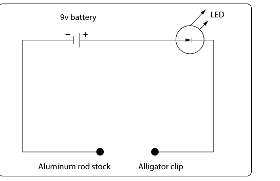
Every aircraft mechanic works with technical drawings daily, and two of the most commonly encountered types in electrical work are the schematic diagram and the pictorial diagram. Although both represent the same underlying electrical system, they do so in fundamentally different ways, and each serves a distinct purpose in the shop and on the flight line. Understanding the difference — and knowing when to use each — is a core competency tested on the FAA Aviation Mechanic General Knowledge Exam and reinforced throughout the FAA Aviation Maintenance Technician Handbook: General (FAA-H-8083-30).
In short, a schematic diagram shows you how a circuit works, while a pictorial diagram shows you what the circuit looks like. Both tools are valuable, but confusing their purposes or misreading their conventions can lead to wiring errors, troubleshooting dead ends, and ultimately unsafe aircraft.
What Is a Schematic Diagram?
A schematic diagram — sometimes called a circuit diagram or wiring diagram — represents an electrical circuit using standardized graphic symbols rather than realistic drawings of components. Each component in the circuit has a universally recognized symbol: resistors appear as zigzag lines or rectangles, capacitors as two parallel lines, switches as a gap in a line with a lever, batteries as a series of alternating long and short parallel lines (each long/short pair representing a cell), grounds as a series of descending horizontal lines, and so on. These symbols are defined by standards that allow any trained technician, regardless of language or country, to read and interpret the circuit correctly.
In a schematic, the physical size, shape, or location of components is completely irrelevant. A relay that is physically mounted at the rear of the aircraft may be drawn right next to a circuit breaker that is located in the cockpit, simply because the diagram is organized around electrical relationships rather than geographic position. Current flow is typically shown moving from left to right or from top to bottom, with the positive supply at one end and the ground return at the other. This logical layout makes it easy to trace a circuit from power source through loads to ground, which is exactly what you need to do when analyzing circuit function or isolating a fault.
Schematics are the first tool to reach for when you want to understand why a circuit behaves a certain way. Want to know whether two components are wired in series or parallel? Look at the schematic. Need to calculate the expected voltage drop across a resistor? The schematic gives you the topology. Want to verify that a relay is normally open or normally closed? The schematic symbol tells you at a glance.
What Is a Pictorial Diagram?
A pictorial diagram, by contrast, represents components as they actually appear — either as realistic illustrations or simplified drawings that resemble the physical part. Wires are shown running in the directions they actually travel through the aircraft, connectors are drawn to look like connectors, and terminal strips are laid out to mirror their real-world arrangement. The goal is spatial accuracy: a technician with little electrical theory background can look at a pictorial diagram, recognize the component they are holding in their hand, and follow the wire to its destination.
Pictorial diagrams are particularly useful during installation and inspection tasks. When you are physically tracing a wire harness, verifying that a connector pin is populated correctly, or confirming that a component is mounted in the right location, a pictorial diagram gives you a map that matches what your eyes actually see. Maintenance manuals often include pictorial diagrams alongside schematics precisely because the two diagrams complement each other: the schematic tells you how the circuit should work, and the pictorial tells you where everything is.
One important limitation of pictorial diagrams is that they can become very cluttered and difficult to read in complex systems. As the number of wires and components grows, realistic drawings overlap and crowd each other. That is why schematics remain the preferred format for sophisticated electrical analysis — a clean schematic can represent an extremely complex circuit in an organized, readable way that a pictorial cannot.
Key Differences Side by Side
- Component representation: Schematics use standardized symbols; pictorials use realistic or semi-realistic images of the actual components.
- Physical location: Schematics ignore physical placement; pictorials reflect actual mounting positions and routing paths.
- Primary use: Schematics are used for circuit analysis, troubleshooting logic, and understanding electrical relationships; pictorials are used for installation, inspection, and physical wire tracing.
- Complexity handling: Schematics remain readable even in complex systems; pictorials become cluttered as system complexity grows.
- Information conveyed: Schematics clearly show series vs. parallel relationships, switch positions, and signal flow; pictorials clearly show connector orientation, harness routing, and component appearance.
How Technicians Use Both Diagrams Together
Skilled AMTs rarely rely on just one type of diagram. A typical troubleshooting workflow might proceed like this: the technician first consults the schematic to understand the circuit's design — identifying the power source, control switches, protective devices, loads, and ground paths. By tracing the schematic, the technician forms a logical theory about where the fault might be located, such as a break in the circuit between the relay coil and the grounding point.
Next, the technician turns to the pictorial diagram (or an accompanying wiring harness diagram) to physically locate the relay, find the connector that contains the relevant ground wire, and confirm which pin number carries that circuit. Armed with both the logical understanding from the schematic and the physical roadmap from the pictorial, the technician can go directly to the right location in the aircraft and perform a targeted voltage or continuity check — saving significant time compared to randomly probing connectors.
Many aircraft maintenance manuals also include two other diagram types that serve different purposes than a straight schematic or pictorial: the isometric wiring diagram and the block diagram. An isometric wiring diagram shows harness routing in three-dimensional physical space, much like a pictorial, helping a technician visualize how bundles run through the actual airframe structure. A block diagram, by contrast, is a highly abstracted view that shows major system components as labeled boxes with connecting lines indicating the direction of signal or power flow, without the symbol-level detail of a schematic or the physical detail of a pictorial. These are useful for systems-level orientation before diving into the detailed schematic.
Key Numbers and Rules
- Schematic symbols used in aviation maintenance documents are generally based on standards published by organizations such as the American National Standards Institute (ANSI) and referenced in FAA-accepted data.
- Wire identification in schematics follows conventions described in FAA Advisory Circulars and the aircraft's manufacturer data — each wire is typically assigned an alphanumeric code that appears on both the schematic and the physical wire bundle label, linking the two diagrams together.
- Ground symbols in a schematic may represent an airframe ground (connection to aircraft structure) or a signal reference ground — knowing which type is shown is critical for troubleshooting voltage measurement problems.
- On the FAA AMT General Knowledge Exam, you may be asked to identify specific schematic symbols (resistor, capacitor, relay coil, diode, fuse, circuit breaker) or to determine whether components in a diagram are connected in series or parallel based on the schematic layout.
- AC and DC circuits use different conventions in some symbols — for example, an AC generator symbol includes a sine wave, while a DC generator symbol does not — and the FAA exam may test recognition of these distinctions.
Common Test Traps
- Confusing schematic location with physical location: A common mistake is assuming that components drawn near each other on a schematic are physically close in the aircraft. They are not — schematics show electrical relationships only, never physical proximity.
- Misreading switch symbols: A normally open (NO) switch symbol shows an open gap, meaning no current flows in the at-rest position. A normally closed (NC) switch symbol shows a completed path at rest. Students sometimes reverse these, leading to incorrect circuit analysis answers.
- Assuming pictorials are always to scale: Pictorial diagrams may simplify routing paths and are not necessarily drawn to scale. Using them to estimate wire lengths or physical distances is a misuse of the diagram type.
- Ignoring ground symbols: Students sometimes trace a circuit on a schematic and miss that the return path goes to airframe ground via the ground symbol rather than a drawn wire. Always follow ground symbols to complete the circuit path.
- Confusing a block diagram with a schematic: Block diagrams show functional relationships between major components but do not contain the symbol-level detail needed for component-level troubleshooting. Reaching for a block diagram when you need a schematic wastes troubleshooting time and can lead to incorrect conclusions.
Mastering the distinction between schematic and pictorial diagrams is more than a test-taking skill — it is a foundational habit of professional aircraft maintenance. When you can fluently move between the logical world of the schematic and the physical world of the pictorial, you work faster, make fewer errors, and build the kind of systematic troubleshooting approach that keeps aircraft airworthy and passengers safe.