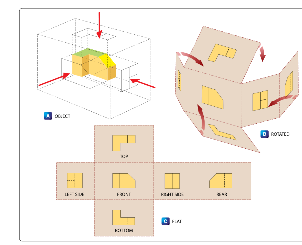
When an aircraft technician needs to fabricate a bracket, repair a structural member, or understand how a component fits into an assembly, a photograph or a single sketch simply isn't enough. A photograph distorts proportions depending on camera angle; a single view hides features on the opposite side. Aviation maintenance relies instead on orthographic projection — a precise, systematic method of showing a three-dimensional object by projecting its true shape onto two or more flat planes that are mutually perpendicular (at 90 degrees) to one another. The result is a set of related views — typically front, top, and right side — that together communicate every dimension, hole, curve, and surface without ambiguity. Every AMT needs to read these drawings fluently, because working from a misunderstood view can produce a part that looks close but is fundamentally wrong.
Orthographic projection is governed by well-established drafting standards. In the United States, aircraft manufacturers follow the conventions of the American National Standards Institute (ANSI) and military/aerospace drawing standards. Understanding the geometric logic behind these conventions is the key to reading any blueprint or engineering drawing you will encounter in an aviation maintenance environment.
The Geometry Behind Orthographic Projection
Imagine placing an object — say, a small aluminum rib — inside a transparent glass box. Each of the six walls of that box represents a projection plane. When you look straight at the front wall and trace the outline and features of the object onto that wall, you produce the front view (also called the front elevation). Rotating 90 degrees and looking at the right side wall produces the right-side view. Looking straight down at the top wall produces the top view (also called the plan view).
To produce a flat drawing, that glass box is then unfolded — imagine cutting the box edges and rotating the walls outward until everything lies in a single plane. This unfolding is the reason the views appear where they do on a standard drawing sheet:
- The top view appears directly above the front view.
- The right-side view appears directly to the right of the front view.
- The left-side view, when included, appears to the left of the front view.
- The bottom view appears directly below the front view.
This arrangement is called third-angle projection, which is the standard used for aircraft drawings in the United States under ANSI conventions. (In many other countries, first-angle projection is used, where the views are arranged in the opposite positions. A small standardized symbol on the title block tells you which convention the drawing uses — always check this first when working with drawings of unknown origin.)
The Three Principal Views
Most aircraft component drawings use three views as the minimum needed to fully describe a part. Each view contributes unique information.
Front View
The front view, sometimes called the elevation view, is considered the primary or most descriptive view. The drafter typically selects the orientation that shows the most characteristic shape of the part as the front view. It establishes the height and width of the object.
Top View
The top view (plan view) is projected from directly above. It shares the same width dimension as the front view — a vertical line dropped from any feature in the top view will align exactly with the same feature in the front view. The top view uniquely reveals the depth (front-to-back dimension) of the object.
Right-Side View
The right-side view is projected from the right and shares the same height as the front view — a horizontal line extended from any feature in the front view will align with the same feature in the right-side view. The right-side view also shows the object's depth, and this depth must match the depth shown in the top view. Drafters often use a 45-degree miter line in the corner between the top and side views to transfer depth measurements accurately.
Lines Used in Orthographic Drawings
Orthographic drawings use a standardized set of line types, each carrying a specific meaning. Misreading a line type is one of the most common errors among technicians new to blueprint reading.
- Visible (object) lines — Thick, solid lines that represent edges and surfaces visible in that view.
- Hidden lines — Medium-weight dashed lines that represent edges or features hidden behind other surfaces in that view. They are critically important: a hole through a part will appear as a solid circle in one view and as hidden (dashed) lines in the adjacent views where it is not directly visible.
- Center lines — Thin lines alternating between a long dash and a short dash, used to show axes of symmetry, the centers of holes, and the paths of circular features. Center lines are not physical edges; they are reference indicators.
- Dimension lines — Thin lines with arrowheads at each end, capped by extension lines, showing the measured distance between two points.
- Cutting-plane lines — Heavy dashed (phantom-style) lines with arrows indicating where the object is cut and the direction of sight for a section view.
- Section lines — Thin diagonal crosshatch lines that fill the cut surface in a section view to indicate the material that was sliced through.
- Break lines — Used when a long, uniform part is shortened on the drawing to save space; they indicate that the actual part continues beyond what is shown.
Section Views and Auxiliary Views
When the interior of a component is complex, an orthographic drawing may include a section view. A cutting plane is passed through the object (shown as a cutting-plane line in the adjacent view), and the object is drawn as if sliced open and the near half removed. The cut surfaces are indicated with section lining (crosshatch lines). Section views reveal internal passages, wall thicknesses, and nested features that would otherwise be buried under confusing layers of hidden lines.
An auxiliary view is used when a surface is inclined — neither parallel nor perpendicular to the standard projection planes. Projecting an inclined surface onto a standard plane produces a distorted, foreshortened shape that cannot be dimensioned accurately. An auxiliary view is projected perpendicular to the inclined surface, showing its true size and shape. Aircraft structures, which are full of compound angles and tapered surfaces, frequently require auxiliary views.
Why Orthographic Projection Matters for AMTs
As an aviation maintenance technician, you will routinely use orthographic drawings to fabricate replacement parts, perform sheet metal repairs, interpret assembly drawings during overhaul, and verify that replaced components match engineering specifications. A misread view can result in a hole drilled in the wrong location, a flange bent in the wrong direction, or a part installed backwards — any of which can create airworthiness concerns.
The FAA's Aviation Maintenance Technician Handbook — General (FAA-H-8083-30) emphasizes that the ability to interpret aircraft drawings is a fundamental skill for all maintenance personnel. Drawing literacy is not optional; it is a safety-critical competency tested on the AMT General knowledge exam.
Key Numbers and Rules
- In third-angle projection (U.S. standard): the top view is above the front view; the right-side view is to the right of the front view.
- In first-angle projection (European standard): the top view is below the front view; the right-side view is to the left of the front view. Always verify the projection symbol in the title block.
- Any dimension shown in the front view's width is shared exactly with the top view's width — you can project a vertical line between them.
- Any dimension shown in the front view's height is shared exactly with the right-side view's height — you can project a horizontal line between them.
- The depth dimension (top-to-bottom in the top view; left-to-right in the right-side view) must be equal in both views — transfer it with a 45-degree miter line or a compass.
- Hidden lines (dashed) always represent features that exist in the object but are not directly visible in that particular view.
- Center lines are never cut or fabricated edges; they indicate axes, symmetry, or the centers of circular features.
Common Test Traps
- Confusing first-angle and third-angle projection: The AMT exam expects you to know that U.S. aircraft drawings use third-angle projection. In first-angle, the views are flipped — top goes below, right side goes left. Always look for the projection symbol on an unfamiliar drawing.
- Treating hidden lines as visible edges: Dashed lines do not show a physical edge you can see; they show a feature hidden behind another surface. Fabricating to a dashed line as if it were a visible edge produces an incorrect part.
- Misidentifying center lines: A center line is not a cut edge; it is an axis indicator. Drilling directly on a center line (rather than using it as the reference to find the center of a hole) is correct — but misidentifying a center line as an edge leads to gross errors.
- Ignoring alignment rules between views: Each pair of adjacent views shares a dimension. If you see a feature in the front view but cannot find its counterpart in the aligned position in the top or side view, you are likely misreading the drawing or the feature is shown as hidden lines.
- Overlooking the need for auxiliary views on inclined surfaces: Students sometimes try to take dimensions from the foreshortened projection of an inclined surface in a standard view. Only the auxiliary view projected perpendicular to that surface shows the true size and shape — and only the auxiliary view should be used for dimensioning inclined features.