Weather radar is one of the most powerful tools available to pilots and meteorologists, but the radar beam does not behave like a flashlight pointed at a flat wall. The beam is subject to the physical laws of wave propagation, atmospheric refraction, and geometric spreading. Understanding these principles is essential for correctly interpreting any radar product—whether you are reviewing a NWS WSR-88D mosaic before departure or monitoring your aircraft's onboard radar in flight. Misreading radar imagery due to beam geometry errors has contributed to pilots inadvertently penetrating severe weather they believed was absent or benign.
This article draws directly from Chapter 15 of the FAA Aviation Weather Handbook (FAA-H-8083-28B) and explains how the radar beam is shaped, how it propagates through the atmosphere, and how three critical geometric phenomena—overshooting, undershooting, and beam blockage—can cause radar to underreport, exaggerate, or completely miss hazardous weather.
How a Radar Beam Is Formed and What It Detects
The WSR-88D (Weather Surveillance Radar—1988 Doppler) uses a parabolic antenna that focuses radio wave energy into a narrow, cone-shaped beam with a beam width of approximately 0.95°. As the beam travels outward from the antenna, it naturally expands in diameter. At 60 NM, this expansion is small enough that two storm cells separated by only 1 NM can be resolved as distinct echoes. At 120 NM, the minimum separation grows to about 2 NM. By contrast, airborne weather radars have beam widths ranging from roughly 3° to 10°—meaning at 60 NM with an average 5° beam, two thunderstorms must be at least 5.5 NM apart to appear as separate echoes.
When pulses of energy from the beam strike a target—precipitation, clouds, dust, terrain, birds, buildings, or wind turbines—a portion of that energy returns to the antenna. This is called backscattered energy, and the radar measures its intensity as reflectivity. The resulting display feature is called an echo. The WSR-88D operates at a peak power output of 750 kW and a wavelength of 10 cm, which allows it to detect even weak, low-reflectivity targets and minimizes the precipitation attenuation that plagues shorter-wavelength systems. Airborne radars typically produce less than 50 kW at a 3 cm wavelength, making them far more susceptible to attenuation and far less capable of detecting subtle targets.
Wave Propagation and Atmospheric Refraction
A radar beam does not travel in a perfectly straight line. Because the atmosphere varies in density with altitude—driven by changes in temperature, moisture, and pressure—the beam bends as it propagates. The physics are straightforward: in a denser portion of the atmosphere the beam travels more slowly, and in a less dense portion it travels faster. Because the beam occupies a finite volume, portions at different densities simultaneously will bend toward the slower (denser) side.
Under normal (standard) atmospheric conditions, density decreases gradually with altitude. This means the top of the beam travels slightly faster than the bottom, causing the beam to curve gently downward. However, the curvature of the beam is less than the curvature of the Earth. The net result is that the beam climbs progressively higher above the Earth's surface as range increases—a critical geometric fact that sets the stage for overshooting.
Overshooting: The Beam Climbs Too High
Overshooting occurs when the radar beam passes entirely over a weather target rather than through it. Under standard refraction this happens naturally with range—at great distances the beam is already thousands of feet above the surface. A WSR-88D scanning at its lowest elevation angle of 0.5° will be roughly 15,000 feet above the ground at 100 NM. Tall convective cells can still be detected, but shallow precipitation systems (low-topped convection, widespread rain, or freezing drizzle) may fall completely below the beam at those distances.
Subrefraction aggravates overshooting. When the atmosphere's density decreases with height faster than the standard rate—meaning the actual density is lower than normal aloft—the beam bends less than it normally would and curves skyward more steeply. The result is that the beam overshoots targets it would otherwise detect under standard conditions. Distant thunderstorms may not appear on the radar image at all. Even when a storm is detected under subrefraction, the beam may strike only the upper reaches of the cumulonimbus cloud, where precipitation particles are smaller and reflectivity is lower. This causes the radar to underestimate storm intensity—a particularly dangerous outcome because the storm may appear weak or moderate on the display when it is actually severe at lower, pilot-relevant altitudes.
Undershooting and Superrefraction
The opposite phenomenon, superrefraction, occurs when the atmospheric density decreases with height more slowly than normal, or even increases with height (a temperature inversion is a classic cause). Under these conditions, the beam bends more sharply toward the Earth's surface than it would under standard refraction. The beam effectively undershoots normal targets and may even strike the ground at ranges much closer than expected.
Superrefraction can produce anomalous propagation (AP), where the beam bends so aggressively that it strikes the terrain or the sea surface and returns strong echoes that appear on the display as precipitation. Pilots and dispatchers reviewing radar imagery may see what looks like widespread precipitation over areas that are, in reality, clear. AP echoes can be recognized by their irregular, stationary, or slowly drifting appearance and their tendency to occur near the radar site—but the distinction is not always obvious. Superrefraction also means the beam may sample lower altitudes than expected at a given range, potentially detecting ground clutter or terrain that contaminates the precipitation analysis.
Beam Blockage
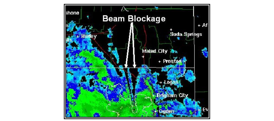
Even if refraction is perfectly normal, the radar beam can be partially or completely obstructed by terrain features, buildings, trees, and other fixed obstacles between the antenna and the target. This is called beam blockage (also referred to as terrain shielding). When the beam is blocked, the energy never reaches the weather target behind the obstacle, and no echo is returned from that sector. On the radar display this appears as a radial blank sector—a wedge-shaped region of no data pointing outward from the radar site.
Beam blockage is not random; it is a fixed, location-specific limitation of each radar site. The NWS accounts for known blockage in its product quality documentation, but pilots using regional radar mosaics may not immediately recognize which blank sectors represent true absence of precipitation versus blocked radials. When flying toward a blank wedge, the correct assumption is that the data is missing—not that the sky is clear. Combining multiple radar sources, examining adjacent tilt angles, or using satellite imagery can help fill in blocked sectors.
Why It Matters to Pilots
These beam geometry limitations have direct safety implications. A pilot who sees no radar echo ahead may conclude it is safe to proceed, when in fact the beam has overshot a line of embedded thunderstorms, a blocked radial hides intense convection, or superrefraction clutter is masking weak returns beyond it. Equally dangerous is the pilot who diverts around what appears to be a strong echo that is actually an AP artifact caused by anomalous propagation near a temperature inversion. The FAA is clear that airborne weather radar should be used to navigate around severe weather, not to penetrate it—and that requires understanding what the radar can and cannot see.
Airborne radar compounds these limitations with its short 3 cm wavelength (high precipitation attenuation), relatively low power output (under 50 kW), wide beam widths (3°–10°), and range attenuation compensation that expires at only 50–75 NM. Beyond that range, targets appear weaker than they actually are. The combination of uncorrected range attenuation and precipitation attenuation means airborne radar in heavy rain may show only the leading edge of extreme echoes, completely hiding what lies beyond the initial cell.
Key Numbers and Rules
- WSR-88D beam width: 0.95°; resolves targets 1 NM apart at 60 NM, 2 NM apart at 120 NM.
- Airborne radar beam width: 3°–10° (average ~5°); resolves targets ~5.5 NM apart at 60 NM, ~10 NM apart at 120 NM.
- WSR-88D peak power: 750 kW; airborne radar typically under 50 kW.
- WSR-88D wavelength: 10 cm (minimal precipitation attenuation); airborne radar ~3 cm (significant attenuation).
- Airborne range attenuation compensation: typically effective only to 50–75 NM; targets beyond appear weaker than actual.
- Subrefraction effect: beam overshoots targets; storms appear weaker or absent.
- Superrefraction effect: beam undershoots; AP ground clutter may appear as precipitation.
- Beam blockage: produces radial blank sectors; absence of echo ≠ absence of weather.
- Normal refraction: beam curves downward but less than Earth's curvature, so height above ground increases with range.
Common Test Traps
- Confusing subrefraction with overshooting: Subrefraction causes the beam to bend less and climb higher, worsening the overshoot problem—not reducing it. Students sometimes invert this.
- Assuming no echo means no weather: Beam blockage and overshooting at long ranges are common causes of missing echoes. Never conclude an area is clear solely because the radar shows nothing.
- Misidentifying anomalous propagation: AP echoes from superrefraction can look like precipitation. Stationary, irregular echoes near the radar site on a clear day should raise suspicion of AP rather than real weather.
- Ignoring airborne radar's attenuation limits: The 3 cm wavelength and low power of airborne radar means it shows only the leading edge of the most intense cells. What appears to be the far side of a storm cell may actually be hidden by attenuation.
- Applying WSR-88D beam resolution numbers to airborne radar: The WSR-88D's narrow 0.95° beam resolves cells 1 NM apart at 60 NM. Airborne radar with a 5° beam cannot do the same—two nearby storms may merge into one echo and appear as a single, traversable gap.