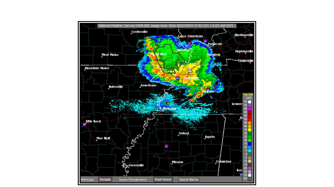
Weather radar is one of the most powerful tools available to pilots and meteorologists for detecting hazardous precipitation, but its output is only as useful as the interpreter's understanding of how it works. A radar image is not a perfect photograph of the atmosphere — it is a mathematical portrait built from reflected radio energy, and every characteristic of that energy, from its wavelength to the way it bends through the atmosphere, shapes what appears on the display. Misreading a radar image has contributed to fatal encounters with convective weather, making this one of the most safety-critical topics in aviation meteorology.
The National Weather Service's Weather Surveillance Radar—1988 Doppler (WSR-88D) is the backbone of weather radar coverage across the United States. Its prototype was built in 1988, and its design choices — wavelength, power, antenna shape, and beam geometry — reflect deliberate engineering trade-offs that every pilot should understand. Airborne weather radar shares the same underlying physics but differs in almost every key parameter, which is why the two tools complement rather than duplicate each other.
How the Antenna Works
A radar antenna alternately transmits pulses of radio-wave energy into the atmosphere and then listens for the return. The WSR-88D uses a parabolic-shaped dish antenna, which focuses the outgoing energy into a narrow, cone-shaped beam. By tilting this antenna through a series of elevation angles, the system can scan multiple altitudes of the atmosphere in a single volume scan. The shape of the antenna directly controls the shape and width of the beam, which in turn determines the system's resolving power — its ability to distinguish one storm from another.
Backscattered Energy and Reflectivity
When the transmitted pulse strikes a target, some fraction of that energy bounces directly back toward the antenna. This returned energy is called backscattered energy. Targets are anything that intercepts the beam: rain, hail, snow, clouds, dust, insects, birds, terrain, buildings, and even wind farm turbines. Reflectivity is the quantitative measurement of how much backscattered energy returns to the antenna. What you see on a radar display — the colored blobs representing precipitation — is called an echo, and it is the visual representation of that reflectivity. Stronger echoes mean higher reflectivity, which generally corresponds to larger or more numerous precipitation particles.
The Radar Equation and Power Output
The underlying physics of how much power returns to the antenna is described by the radar equation. In simplified terms, the received power depends on the transmitted power, the antenna's gain, the wavelength, the range to the target, and the reflectivity of the target itself. Because power spreads over an ever-increasing area as it travels outward (following an inverse-square relationship with range), a target that is twice as far away returns only a fraction of the power of an identical closer target. This is the basis of range attenuation, discussed below.
The WSR-88D has a peak power output of approximately 450 kilowatts (kW). This enormous power budget is what allows the network to detect very low-reflectivity targets such as clouds, dust, and insects. Most airborne weather radars, by contrast, have a peak power output of less than 50 kW. That roughly 9-to-1 power difference means airborne radar struggles to detect the same small, weakly reflective targets that the WSR-88D sees clearly. For pilots, this means airborne radar is best suited for detecting heavy precipitation cores — not for identifying every cloud or boundary in the vicinity.
Wavelength
The wavelength is the distance between successive crests (or troughs) of the emitted radio wave. The WSR-88D operates at a wavelength of 10 centimeters (cm), placing it in the S-band of the radio-frequency spectrum. Most airborne weather radars operate at 3 cm, in the X-band. Shorter wavelengths interact more strongly with smaller particles, which is an advantage for sensitivity, but they suffer a major operational penalty: they are attenuated far more aggressively by precipitation. This trade-off is central to understanding the limitations of airborne radar.
Attenuation: The Hidden Hazard in Radar Interpretation
Attenuation is any process that removes energy from the radar beam, reducing the backscattered signal that returns to the antenna. Two forms are operationally important.
Precipitation Attenuation
Precipitation attenuation occurs when precipitation particles along the beam path absorb and scatter the radar energy before it can reach more distant targets. The result is that storm cells behind a heavy precipitation core may appear weaker than they actually are, or may not appear at all. Because attenuation increases sharply as wavelength decreases, the WSR-88D's 10-cm wavelength is not significantly attenuated by most precipitation, giving it a relatively clear view through the atmosphere. Airborne radar's 3-cm wavelength, however, suffers significant precipitation attenuation. In practice, this means that when an airborne radar is pointed at an intense storm, it typically shows only the leading edge of the most extreme echoes. The storm may be far larger and deeper than the display suggests, and additional cells hidden behind the first line of precipitation are simply invisible. This is a potentially lethal misread: a pilot might believe the gap between two echoes is clear air, when in reality it is just a radar shadow.
Range Attenuation
Range attenuation is the natural weakening of the signal with increasing distance from the antenna, a direct consequence of energy spreading over a larger area. Without correction, a storm 120 NM away would look much weaker than an identical storm 30 NM away. The WSR-88D automatically compensates for range attenuation across its entire operational range. Most airborne radars, however, only apply range-attenuation compensation out to 50 to 75 nautical miles (NM). Beyond that distance, targets will appear less intense than they actually are on the airborne display — another reason to treat long-range airborne radar returns with caution.
Resolution: Seeing Storms as Separate Targets
Resolution is the radar's ability to display two nearby targets as distinct echoes rather than merging them into one. Beam resolution specifically refers to the ability to separate targets at the same range but different azimuths; two targets must be separated by at least one beam width to appear as separate echoes.
The WSR-88D has a beam width of 0.95°. At 60 NM, this corresponds to roughly 1 NM of lateral separation required to resolve two distinct storms. At 120 NM, approximately 2 NM of separation is needed. Airborne radar beam widths typically range from 3° to 10°. At an average of 5°, two storm cells at 60 NM must be at least 5.5 NM apart to appear separately on the display; at 120 NM, the required separation grows to about 10 NM. In practical terms, two thunderstorms that look like a single merged blob on airborne radar may be clearly resolved as two distinct cells on a WSR-88D image. Equally important, beam resolution decreases with range for any radar — a seeming gap or break in a line of precipitation at long range may close up or disappear as the line moves closer, not because new cells formed, but because the improving resolution is now revealing what was always there.
Wave Propagation: How the Beam Bends
Radar beams do not travel in perfectly straight lines. Variations in atmospheric temperature, moisture, and pressure create density gradients, and the beam bends toward regions of higher density (where the wave travels more slowly), exactly as light bends when passing through media of different optical densities.
Under normal (standard) refraction, atmospheric density decreases gradually with altitude, causing the upper portion of the beam to travel slightly faster than the lower portion. This bends the beam gently downward. However, the Earth's surface curves away faster than the beam bends, so the beam's altitude above the surface still increases with range — meaning distant low-level features may be missed entirely (the beam passes over them).
Subrefraction occurs when atmospheric density decreases with altitude faster than normal. The beam bends less than usual and tends to shoot upward. This can cause the beam to overshoot distant low-altitude targets such as low-topped convective cells or terrain features, and it may cause storms to appear weaker because the beam strikes the upper, ice-crystal portions of a cumulonimbus where reflectivity is lower.
Superrefraction is the opposite condition: density decreases with altitude slower than normal, or even increases with altitude. The beam bends more than usual toward the Earth's surface. In extreme cases, superrefraction can produce anomalous propagation (AP), where the beam actually strikes the ground or sea surface and returns a false echo that resembles precipitation on the display. Pilots and controllers must learn to distinguish AP returns from genuine weather echoes.
Key Numbers and Rules
- WSR-88D peak power: approximately 450 kW; airborne radar typically less than 50 kW
- WSR-88D wavelength: 10 cm (S-band); airborne radar typically 3 cm (X-band)
- WSR-88D beam width: 0.95°; airborne radar beam widths range from 3° to 10°
- Airborne range-attenuation compensation: typically only out to 50–75 NM
- Beam resolution at 60 NM: WSR-88D ~1 NM separation needed; airborne (5° beam) ~5.5 NM
- Beam resolution at 120 NM: WSR-88D ~2 NM; airborne (5° beam) ~10 NM
- Shorter wavelength = greater precipitation attenuation (3-cm airborne radar attenuates significantly; 10-cm WSR-88D does not)
Common Test Traps
- Assuming airborne radar shows the whole storm: Because of precipitation attenuation at 3 cm, airborne radar typically shows only the leading edge of extreme echoes. Cells hidden behind a heavy rain shaft will not appear.
- Ignoring range-attenuation limits on airborne radar: Beyond 50–75 NM, airborne radar returns are not range-compensated, so distant storms look weaker than they are. The WSR-88D does not have this limitation.
- Misreading resolution improvements as new storm development: When a seemingly solid line of precipitation breaks into separate cells as it moves closer to the radar, this is a resolution artifact, not actual dissipation. The gaps may have existed all along but were invisible at long range.
- Confusing subrefraction and superrefraction effects: Subrefraction causes the beam to overshoot targets (storms appear weaker or absent); superrefraction bends the beam toward the ground and can create false echoes (anomalous propagation).
- Assuming reflectivity equals intensity directly: Reflectivity measures backscattered energy, which is primarily tied to precipitation particle size and number — but attenuation, beam geometry, and propagation effects can all cause the displayed reflectivity to understate the actual storm intensity.