Of all the insidious threats to a reciprocating aircraft engine, carburetor icing stands out because it can develop rapidly, in conditions that feel completely benign, and without any dramatic warning. A pilot or mechanic who understands only that "carb ice forms when it's cold and wet" is dangerously under-prepared. The carburetor heat system is an elegantly simple countermeasure built into virtually every carbureted light-aircraft powerplant, but its effectiveness depends entirely on correct design, proper maintenance, and disciplined operation. This article examines the physics of carburetor icing, the mechanical design of the heat system, maintenance considerations for Aviation Maintenance Technicians (AMTs), and the operational discipline required to keep the engine running.
Why Ice Forms in the Carburetor
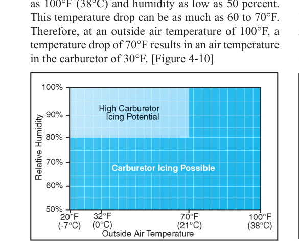
A float-type carburetor mixes fuel and air in a precise ratio by accelerating intake air through a venturi. Two simultaneous physical processes make the carburetor throat extremely prone to ice formation. First, as air accelerates through the venturi, its pressure drops sharply. According to Bernoulli's principle, that pressure drop produces a corresponding temperature drop — the FAA cites a drop of up to 60°F to 70°F below the incoming air temperature in some cases. Second, when fuel is introduced and atomized, it absorbs additional latent heat as it vaporizes, dropping the local temperature another 20°F to 30°F or so. The combined effect can push carburetor throat temperature well below freezing even when outside air temperature (OAT) is as high as 70°F (21°C) with high relative humidity.
The FAA's Pilot's Handbook of Aeronautical Knowledge (FAA-H-8083-25) identifies three types of carburetor ice based on the source of the moisture: fuel evaporation ice, caused by the cooling from fuel vaporization; throttle ice, which forms on or just downstream of a partially-closed throttle plate where a pressure drop is sharpest; and impact ice, which forms when supercooled water droplets or visible moisture physically strike and freeze on the carburetor air intake and screen. Of these, fuel evaporation ice and throttle ice are the most common and most deceptive because they form in clear air.
The classic high-risk scenario is a day with OAT in a wide range — generally cited from roughly 20°F to 100°F — and relative humidity generally above 50%, per FAA carburetor icing probability charts. Many accidents have occurred on pleasant summer days at reduced power settings — exactly when throttle-induced pressure drops are greatest and many pilots are least vigilant. The Aviation Weather Handbook (FAA-H-8083-28) reinforces this: high humidity and moderate temperatures create the most dangerous carburetor icing conditions, more so than cold, dry air where there is little moisture available to freeze.
How the Carburetor Heat System Works
The carburetor heat system is a manually operated alternate air source that routes heated air — rather than outside ram air — into the carburetor. In the vast majority of light aircraft, this heated air is drawn from a shroud or muff wrapped around a section of the exhaust system, typically the exhaust manifold or a dedicated heat exchanger attached to one of the exhaust stacks. Engine exhaust gases passing through the shroud heat the surrounding air, and when the pilot or technician opens the carburetor heat valve (often called the carb heat control), a butterfly or flap valve redirects the induction airflow from the outside ram-air inlet to this pre-heated alternate source.
The system has several key design characteristics that AMTs must understand and maintain:
- Heat source adequacy: The exhaust muff must transfer enough heat to raise induction air temperature sufficiently to melt ice already formed or to prevent ice from forming. FAA-certificated designs are tested to ensure adequate heating; deteriorated or improperly repaired muffs may not deliver adequate heat.
- No filtration in the alternate air path: Unlike the normal induction path, which passes through an air filter, carburetor heat air is typically unfiltered. This is acceptable in flight because the alternate air inlet faces away from contamination, but it means operating carb heat on the ground (where dust and debris are present) for extended periods is undesirable.
- Mixture enrichment effect: Hot air is less dense than cold ram air. When carburetor heat is applied, the engine receives less oxygen per unit volume, effectively enriching the mixture. This produces a slight, temporary roughness and a small RPM drop — both are normal and expected. As ice melts and is ingested through the engine, additional roughness occurs temporarily. If applying carb heat is followed by an RPM rise after the initial drop, that is a good indicator that ice was present and is now melting.
- Partial heat is dangerous: Applying insufficient heat can accelerate ice formation by warming the venturi just enough to increase moisture but not enough to prevent freezing. Carb heat should be applied fully — all the way in — not partially.
Maintenance Considerations for AMTs
From a powerplant maintenance perspective, the carburetor heat system demands careful inspection at every annual and at progressive checks. The following areas are critical:
Exhaust heat muff integrity: The exhaust muff or heat exchanger is one of the most safety-critical components in the induction system. Cracks or pinholes in the muff allow carbon monoxide (CO) — a product of combustion — to enter the induction air stream and ultimately the cockpit via the carburetor and intake tract. The Aviation Maintenance Handbook — Airframe (FAA-H-8083-31) and the engine manufacturer's maintenance manuals both emphasize that the heat muff must be inspected for cracks, corrosion, and leakage. A cracked muff is an immediate airworthiness concern. Inspectors use a bright light and mirror, and some shops use a pressure-decay test on the exhaust system to detect leaks.
Carburetor heat box and control rigging: The flap or butterfly valve inside the carb heat box must move fully and freely to both the full-cold and full-hot positions. Control cable or rod rigging must be inspected for correct travel, security, and freedom from binding or chafing. A carb heat control that feels like it is fully applied but leaves the valve partially open provides the dangerous partial-heat condition described earlier.
Alternate air door condition: The door or flap that seals the outside air path when carb heat is selected must seat properly and not leak in either position. Deteriorated seals or a warped door can allow partial mixing of hot and cold air, reducing system effectiveness.
Carburetor airbox and filter: The main air filter must be clean and properly seated. A clogged filter increases the pressure differential across it, making the alternate (carb heat) air path more likely to be needed even when icing is not the issue, and it exaggerates the RPM effect when carb heat is applied.
Operational Use — Key Numbers and Rules
The operational guidance for carburetor heat is found in both the aircraft's FAA-approved Pilot's Operating Handbook (POH)/Airplane Flight Manual (AFM) and in FAA-H-8083-25. General principles include:
- Use carb heat before reducing power — especially before descent, approach, and landing — because throttle ice forms rapidly at low power settings.
- Apply carb heat fully — partial application is worse than none, as described above.
- Expect a normal RPM drop in a fixed-pitch aircraft when carb heat is applied in ice-free conditions; the exact magnitude varies by aircraft and engine and is specified in the POH/AFM rather than by a single universal figure. An RPM drop is normal; an RPM rise after the initial drop indicates ice was present and is melting.
- Monitor for ice conditions using published carb icing probability charts (found in FAA-H-8083-28) based on OAT and dew point spread. When OAT is moderate and humidity is high, routine periodic carb heat checks during cruise are appropriate.
- Do not use carb heat during takeoff in most aircraft — the POH for most trainers prohibits carb heat at full power takeoff because the unfiltered, less-dense hot air reduces performance. Always verify with the specific aircraft's POH.
- On the ground, limit carb heat use to the brief check during run-up. Extended ground operation with carb heat subjects the engine to unfiltered air and excess heat.
Memory Aid
A widely taught cockpit reminder for when carb icing risk is high uses the phrase "HEAT before DESCENT" — not an official FAA acronym, but a practical reminder that the highest-risk period for throttle ice is the power reduction before descent or approach. More formally, some instructors use the weather correlation reminder "Warm and Wet — Beware" to prompt checking carb ice probability charts whenever OAT is moderate and humidity is elevated. Neither replaces consulting the POH and the icing probability chart, but both reinforce the counterintuitive reality that mild, humid days are more dangerous than cold, clear days.
Common Test Traps
- "Carb ice only forms in cold weather." False. The FAA repeatedly emphasizes that carburetor icing can occur at OAT as high as 70°F (21°C) or higher. Moderate temperatures and high humidity are the prime conditions — not extreme cold.
- Confusing the RPM response. When carb heat is applied, the initial effect is always a slight RPM drop (due to less-dense hot air). An RPM rise that follows indicates melting ice being cleared — a strong indicator that ice was present. A sustained RPM drop with no subsequent rise means no ice was present, which is also acceptable.
- Partial carb heat. Many exams test whether students know that partial application can accelerate ice formation. Always apply carb heat fully, never halfway.
- Cracked exhaust muff = CO hazard. AMT exams often test that a deteriorated carburetor heat muff is not merely an induction efficiency problem — it is a carbon monoxide poisoning hazard that renders the aircraft unairworthy.
- Carb heat during takeoff. Most POHs prohibit applying carb heat at full power for takeoff. Using it reduces power output and introduces unfiltered air. The run-up check verifies function; carb heat is then turned off before the takeoff roll.