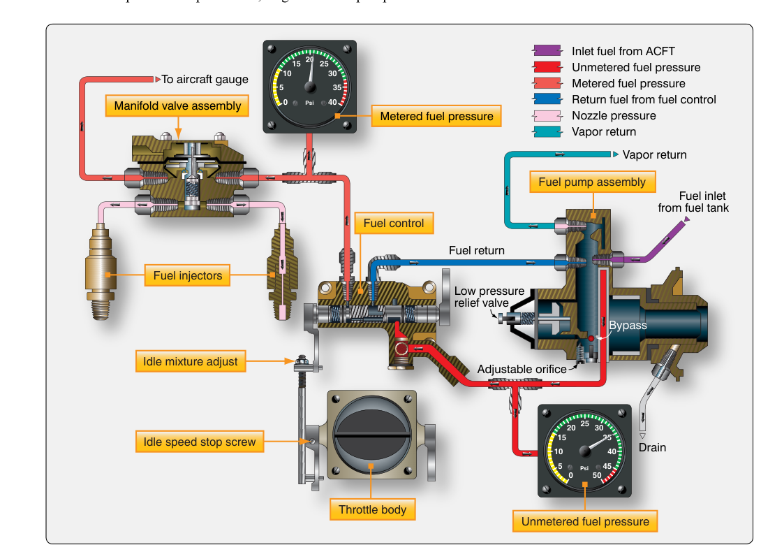
On many modern piston-powered aircraft, the carburetor has been replaced by a continuous-flow fuel injection system. Rather than relying on a venturi and float bowl to draw and mix fuel with air, this type of system meters and delivers fuel at a constant, regulated rate directly to each cylinder's intake port. The result is improved fuel distribution, better throttle response, reduced icing risk, and more precise mixture control — all critical factors in both safety and performance for certificated aircraft engines.
Understanding how a continuous-flow fuel injection induction system works is essential knowledge for any Aviation Maintenance Technician (AMT) seeking a Powerplant certificate. The FAA tests this material directly, and real-world maintenance decisions — from diagnosing rough running to performing flow checks — depend on a solid grasp of the underlying principles.
How the System Works
A continuous-flow fuel injection system, such as the Bendix RSA-type or the TCM (Teledyne Continental Motors) system found on many Lycoming- and Continental-powered aircraft, consists of several integrated components that work together to deliver the correct fuel-to-air ratio under all operating conditions. Unlike a pulsed (port) injector common in automotive engines, this system provides a continuous stream of fuel — hence its name — rather than timed injection pulses.
The Fuel-Air Control Unit (Fuel Control)
At the heart of the system is the fuel-air control unit, sometimes called the fuel control or fuel metering unit. This device senses two key parameters: air mass flow entering the engine (via a venturi or impact tube) and mixture control position. By measuring the differential pressure across the venturi, the unit automatically increases fuel delivery when more air enters and decreases it when air mass drops — for example, during a throttle reduction or a climb to higher altitude. This automatic compensation is one of the major advantages of continuous-flow injection over a float-type carburetor, which must rely on pilot mixture adjustment to compensate for density altitude changes.
The mixture control allows the pilot or technician to manually alter the fuel-to-air ratio. At the full-rich setting, maximum fuel flow is supplied for takeoff power; at the lean setting, fuel flow is reduced to optimize cruise efficiency or facilitate engine shutdown. Many systems include a idle cutoff position that completely stops fuel flow, providing a clean shutdown without diesel-style run-on.
The Fuel Manifold Valve (Flow Divider)
Fuel metered by the control unit passes to the fuel manifold valve, also called the flow divider. This spring-loaded valve serves two important functions. First, it distributes fuel equally to each individual injector nozzle. Second, because it is spring-loaded, it remains closed at very low fuel pressures — specifically during engine shutdown — preventing fuel from dribbling into the intake ports when the engine is not running. This prevents the hot-start flooding problem common if residual fuel vaporizes in the lines after shutdown.
When the engine is cranked and fuel pressure builds above the spring's cracking pressure, the flow divider opens, allowing fuel to flow simultaneously to all cylinders. This simultaneous, continuous delivery is the defining characteristic of the system and is what distinguishes it from timed injection architectures.
Injector Nozzles
Each cylinder receives fuel through a dedicated injector nozzle mounted in or near the intake port. The nozzle is a calibrated orifice — its opening size is carefully sized and matched across all cylinders. Air enters the nozzle shroud from outside the engine (or from the induction air box), atomizing the fuel as it exits the orifice. This air-bleed design helps break the fuel stream into fine droplets for atomization, improving fuel distribution as the mixture travels into the cylinder.
Because each cylinder receives its own nozzle with its own dedicated line, fuel distribution is far more uniform than in a carburetor-based induction system, where fuel distribution between cylinders depends heavily on intake manifold geometry and runner length. Uneven distribution causes some cylinders to run rich while others run lean — a known contributor to rough running and reduced power. Continuous-flow injection largely eliminates this problem, though nozzle clogging or line restrictions can still cause distribution imbalances.
Induction Airflow Path
The air entering the system follows a path from the air filter (or alternate air source) through the throttle body and into the fuel-air control unit. The throttle butterfly valve controls the volume of air allowed to enter. Unlike a carburetor, there is no venturi restriction at the main airflow passage sized to draw fuel; the venturi in a continuous-flow system is a sensing element only. This less-restrictive airflow path is one reason injection systems can deliver slightly more power than comparable carbureted engines — reduced intake restriction improves volumetric efficiency.
An alternate air door (or alternate induction air valve) provides a backup air source that bypasses the main filter. If the filter becomes blocked by icing or contamination, the pilot opens the alternate air door (or in some installations it opens automatically), drawing unfiltered air directly from inside the engine compartment. This air is warmer and at a slightly different pressure, so some power reduction is expected, but the engine continues to run.
Why It Matters
From a maintenance standpoint, understanding this system matters for several reasons. First, fuel injection systems largely eliminate induction icing. Because there is no venturi-induced pressure drop and no fuel vaporization occurring inside a mixing chamber, the dramatic temperature drop that causes carburetor ice simply does not occur in the induction air path of an injection system. The FAA notes this as a principal advantage in the Aviation Maintenance Technician Handbook — Powerplant. However, maintenance personnel must still be aware that impact ice (ice forming on the air filter or inlet) can affect injected engines, making the alternate air system equally critical.
Second, continuous-flow injection supports more precise mixture leaning, which directly affects engine longevity and fuel economy. When a pilot can lean accurately by referencing fuel flow gauges and exhaust gas temperature (EGT), cylinder head temperatures are better managed and lead-fouled spark plugs are reduced — all of which translates into lower maintenance costs over time.
Third, because all critical fuel-delivery components are external to the engine and accessible, troubleshooting and maintenance are more straightforward than diagnosing internal carburetor wear. Flow checks and nozzle cleaning are standard scheduled maintenance tasks for injection-equipped engines.
Key Numbers and Rules
- Flow divider cracking pressure: The manifold valve spring is calibrated to open only when fuel pressure reaches a defined threshold (specific to the engine model), preventing fuel dribble at shutdown.
- Nozzle calibration: All injector nozzles on a given engine must be of the same calibration (flow rate). Mixing nozzle sizes causes cylinder-to-cylinder fuel imbalance — a common AMT test point.
- Idle mixture adjustment: Proper idle mixture is verified by the idle cutoff check: as the mixture is slowly moved to idle cutoff, a momentary RPM rise of roughly 25–50 RPM is generally accepted (per engine manufacturer service instructions, e.g., Lycoming/Continental) as indicating a correct idle mixture; exact figures can vary by engine model, so always confirm against the applicable manufacturer maintenance manual. A larger rise indicates an overly rich idle.
- Alternate air: Activating alternate air on an injection-equipped aircraft provides warmer, unfiltered air and may cause a small power reduction, but does not produce the large power loss associated with carburetor heat because there is no choke venturi to bypass.
- Scheduled maintenance: Injector nozzles should be cleaned and flow-checked at intervals specified by the engine manufacturer's Instructions for Continued Airworthiness (ICA). Carbon buildup at the nozzle tip is the most common maintenance finding.
- Fuel system certification: Fuel injection system components on certificated aircraft are subject to FAA approval under 14 CFR Part 33 (airworthiness standards for aircraft engines) and must be maintained per the manufacturer's approved maintenance manual.
Common Test Traps
- Confusing injection with carburetion on icing: Injection systems are NOT immune to all forms of ice. Impact ice at the air inlet can restrict airflow on an injected engine just as effectively as carburetor ice — only the mechanism of induction (venturi/fuel-evaporation) ice is eliminated.
- Misidentifying the flow divider's role: The fuel manifold valve (flow divider) is not simply a check valve — it also ensures simultaneous, equal fuel distribution to all cylinders and prevents post-shutdown fuel dribble into intake ports. Test questions often ask specifically about why the spring-loaded valve is necessary.
- Idle cutoff check interpretation: Students sometimes think any RPM rise during idle cutoff check is bad. In fact, a small rise (roughly 25–50 RPM, per manufacturer guidance) indicates correct idle mixture; a decrease or no rise generally suggests an overly lean idle, while a large rise confirms an overly rich idle setting.
- Nozzle air bleed misidentified: The air bleed in each injector nozzle shroud is for atomization, not for mixture control. Mixture is controlled exclusively at the fuel-air control unit. Blocking the nozzle air bleed causes rich running at that cylinder — a tested maintenance pitfall.
- Alternate air vs. carburetor heat: On injection systems, alternate air is primarily an anti-blockage measure, not a de-icing device. Unlike carburetor heat (which heats air to melt venturi ice), alternate air simply provides a bypass path around a blocked filter. The two systems serve similar but distinct purposes and must not be confused on the written exam.