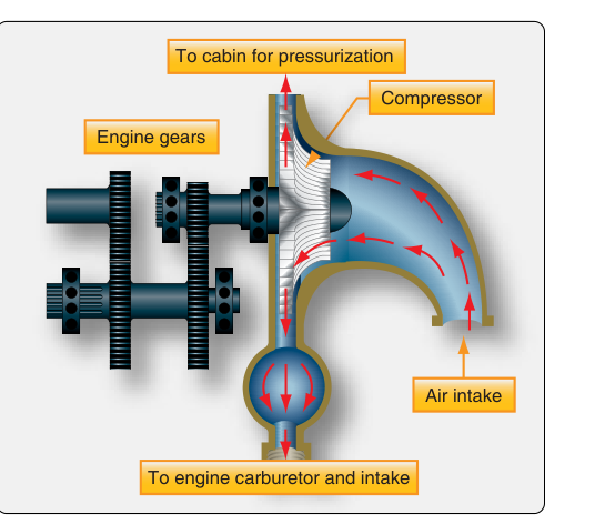
The induction system is the pathway through which an aircraft reciprocating engine draws in the air — and often the air-fuel mixture — needed for combustion. Every design decision in an induction system, from the shape of the intake duct to the presence or absence of a compressor, directly affects how much power the engine can produce, how reliably it operates across a wide range of altitudes and temperatures, and how the powerplant responds to the pilot's and mechanic's inputs. For the AMT powerplant technician, a thorough understanding of induction system types and configurations is not just an exam requirement — it is foundational knowledge that informs inspection, troubleshooting, and airworthiness decisions on a daily basis.
At its core, every induction system must accomplish three tasks: admit a measured quantity of clean air, mix that air with fuel in the correct proportion, and deliver the combustible mixture to each cylinder with minimum restriction and maximum uniformity. How each system accomplishes these tasks — and what trade-offs it accepts — defines the category to which it belongs.
Naturally Aspirated (Normally Aspirated) Systems
The simplest and most common type found on light general aviation aircraft is the naturally aspirated, or normally aspirated, induction system. In this configuration, the engine relies entirely on atmospheric pressure to push air through the intake tract and into the cylinders during the intake stroke. There is no mechanical device to compress the incoming charge beyond ambient pressure.
A typical naturally aspirated induction system begins at an alternate air door or a ram air inlet — usually located on the engine cowling — that faces the slipstream to take advantage of ram effect at cruise speeds. Air then passes through an air filter, which removes dust, debris, and insects. From there, on carburetor-equipped engines, the airflow enters the carburetor venturi, where fuel is metered and vaporized into the airstream. On fuel-injected engines, the air travels through a throttle body and fuel-air control unit, and fuel is injected either at the individual cylinder intake ports or directly into the cylinder.
Because the engine depends entirely on ambient pressure, power output decreases predictably with altitude. As a rule of thumb, a normally aspirated engine loses approximately 3 percent of its sea-level power for every 1,000 feet of altitude gain. At 8,000 feet density altitude, an engine rated at 200 horsepower at sea level might produce only around 160 horsepower. This characteristic makes normally aspirated engines best suited for operations at lower altitudes, typically below 12,000 feet density altitude in practical terms.
Supercharged Induction Systems
To recover the power lost at altitude, engineers add a compressor to the induction system. When that compressor is driven mechanically — directly off the engine's crankshaft or accessory gearing — the system is called a supercharger. Superchargers are classified as internal or external depending on where the compressor is placed relative to the engine's induction tract.
An internally driven supercharger (also called a gear-driven supercharger) uses an impeller spinning inside a diffuser housing. The impeller is driven through a gear train at a speed many times the crankshaft speed, often 6:1 to 10:1 or higher. As air (or mixture) is accelerated radially outward by the impeller and then slowed in the diffuser, its pressure and temperature rise. The now-denser charge is delivered to the intake ports of each cylinder, allowing the engine to maintain rated manifold pressure at altitudes where the atmosphere alone could not supply it.
Two sub-types are worth understanding: single-stage superchargers use one impeller and are common on engines designed for moderate altitude use. Two-stage superchargers add a second impeller and intercooler to reach higher manifold pressures while keeping charge temperature within acceptable limits. The intercooler — a heat exchanger between the two stages — removes some of the heat of compression to prevent detonation.
Because the supercharger is geared to the crankshaft, it consumes a portion of engine output (parasitic loss) at all times, including at low altitude where extra compression is not needed. To manage this, many supercharged engines use a regulating valve (sometimes called a throttle or bootstrapping valve) and a pressure ratio controller to avoid overboosting the engine at lower altitudes.
Turbocharged Induction Systems
The turbocharger (technically a turbosupercharger) accomplishes the same compression goal as the gear-driven supercharger but uses a different power source: the energy of exhaust gases. Hot exhaust from the engine spins a turbine wheel at very high speed — commonly 80,000 to 120,000 RPM — and the turbine wheel shares a common shaft with a centrifugal compressor (the compressor wheel). The compressor draws in ambient air, compresses it, and delivers it to the engine's induction system. Because exhaust energy that would otherwise be wasted is doing the compression work, the parasitic power loss of a turbocharger is far smaller than that of a gear-driven supercharger.
Key Turbocharger Components
- Turbine housing and wheel: Located in the exhaust path; the turbine extracts energy from exhaust gases to drive the compressor.
- Compressor housing and wheel: Located in the induction path; spins with the turbine to compress incoming air.
- Center housing (bearing section): Contains the shaft bearings, lubricated by engine oil supplied through dedicated oil lines.
- Wastegate: A butterfly valve in the exhaust path that bypasses exhaust around the turbine. By controlling how much exhaust reaches the turbine, the wastegate regulates compressor output and prevents overboosting. Wastegates may be manually controlled, automatically controlled by an absolute pressure controller, or both.
- Absolute pressure controller (APC): Automatically positions the wastegate to maintain a preset upper limit of manifold pressure, protecting the engine from inadvertent overboost.
- Density controller: Limits the maximum pressure at the compressor outlet at full-throttle settings, commonly used in conjunction with the APC.
- Differential pressure controller: Maintains a constant pressure differential across the fuel-air control unit at partial throttle settings, improving fuel scheduling accuracy.
- Intercooler/aftercooler: A heat exchanger between the compressor outlet and the throttle body that reduces charge temperature, lowering the risk of detonation and improving volumetric efficiency.
Turbocharged engines can be configured in two important operational modes. In ground boosting (or sea-level boosting), the turbocharger allows the engine to produce more than its rated sea-level power, effectively increasing total output. In altitude turbocharging (or normalizing), the turbocharger is used only to maintain sea-level manifold pressure as altitude increases — the engine produces rated power up to its critical altitude, the altitude above which the turbocharger can no longer maintain rated manifold pressure even with the wastegate fully closed.
Fuel Injection vs. Carburetor Induction Configurations
The fuel-metering method profoundly affects induction system design. Carbureted engines expose the fuel-air mixture to the full length of the intake manifold, creating a risk of carburetor ice — the deposit of ice in the carburetor venturi due to the combination of fuel vaporization cooling and atmospheric moisture. Carburetor heat systems address this by routing warm air from a heat muff around the exhaust pipes to the carburetor air inlet. Fuel-injected engines avoid this particular icing risk in the venturi but remain susceptible to impact ice blocking the air inlet and to induction system icing in the throttle body.
Fuel-injected induction systems also face a unique challenge: vapor lock and hot starting. Because individual cylinder fuel lines carry fuel close to hot engine components, residual fuel can vaporize after shutdown, creating difficulties re-establishing flow on a hot start. Many fuel-injected engines include a fuel-return line and specific priming procedures to purge vapor.
Why Induction System Type Matters for Maintenance
AMT powerplant technicians must appreciate that induction system integrity is directly tied to engine airworthiness. Induction system leaks — even small cracks or loose clamps downstream of the throttle body — create unmetered air (lean mixture) that can lead to rough running, overheating, or engine failure. Leaks upstream of the throttle introduce unfiltered air that can cause accelerated cylinder wear. Turbocharger oil leaks can contaminate the induction air with oil, fouling spark plugs and increasing fire risk. Every annual inspection and 100-hour inspection includes a thorough check of all induction system hoses, clamps, gaskets, and heat muff integrity.
Key Numbers and Rules
- Normally aspirated engines lose approximately 3% of sea-level rated power per 1,000 feet of density altitude increase.
- Turbocharger shaft speeds typically range from 80,000 to 120,000 RPM — never touch or spin a turbocharger by hand without following specific maintenance procedures, as bearing damage can result.
- Engine oil supplied to the turbocharger center section must be clean and at proper pressure; the turbocharger must not be shut down abruptly at high power — a cool-down period at low power (typically 1-2 minutes) is required to prevent oil coking in the bearing housing.
- The wastegate in the fully open position sends maximum exhaust flow around the turbine, minimizing boost; fully closed directs all exhaust through the turbine for maximum compression.
- Carburetor heat is applied using full hot — partial application can cause ice to form rather than melt it, temporarily worsening conditions.
- Induction air filters must be inspected and serviced per the engine manufacturer's maintenance manual; a clogged filter restricts airflow and enriches the mixture.
Common Test Traps
- Supercharger vs. turbocharger power source: The exam frequently tests whether candidates know that a supercharger is gear-driven (crankshaft power) while a turbocharger is exhaust-gas driven. Confusing the two is one of the most common errors.
- Wastegate position and boost: Many students assume a closed wastegate means less boost. In fact, a fully closed wastegate forces all exhaust through the turbine, producing maximum boost. Open wastegate = less boost.
- Critical altitude definition: The critical altitude is not the engine's service ceiling — it is the highest altitude at which the turbocharger can maintain the engine's rated manifold pressure at full throttle.
- Carburetor ice versus impact ice: Carburetor ice forms in the venturi due to vaporization cooling and moisture; impact ice blocks the air inlet due to supercooled water or snow. They require different responses (carburetor heat vs. alternate air), and the exam tests whether students can distinguish them.
- Induction leak symptoms: A lean mixture at all power settings that cannot be corrected with the mixture control, combined with rough running, often indicates a downstream induction leak — not a fuel system problem. Students sometimes reach for the fuel system as the cause.