Every wire in an aircraft electrical system has resistance, and that resistance causes a small but important loss of voltage as current flows through it. This phenomenon, called voltage drop, is the difference between the voltage supplied at the power source and the voltage actually available at the load — a light, motor, avionics box, or any other consuming device. When voltage drop is too large, equipment may malfunction, fail to operate within its rated specifications, or fail altogether. In severe cases, an undersized wire carrying more current than it is designed for will heat up, potentially scorching insulation, causing shorts, or igniting fires hidden deep inside a wiring bundle.
Selecting the correct wire gauge for every circuit is therefore one of the most safety-critical tasks an aviation maintenance technician (AMT) performs. This article explains the physics of voltage drop, walks through the selection method described in FAA maintenance guidance, and highlights the practical and exam-relevant points every AMT candidate must know.
How Voltage Drop Works
Ohm's Law states that voltage equals current multiplied by resistance: E = I × R. Every conductor has measurable resistance that depends on three factors: the material it is made from, its length, and its cross-sectional area. Aircraft wire is almost always made from copper or aluminum; copper is far more common because it offers lower resistance per unit length and excellent flexibility.
As wire gets longer, its total resistance increases proportionally — double the length, double the resistance. As the cross-sectional area increases (a larger gauge wire), resistance decreases because more metal is available to carry current. The American Wire Gauge (AWG) system — also called the Brown & Sharpe gauge — assigns numbers to wire sizes, and here is where a critical counter-intuitive fact trips up many students: a larger AWG number means a smaller, thinner wire. AWG 22 wire is significantly thinner than AWG 4 wire. The scale runs roughly from AWG 0000 (extremely heavy) down to AWG 28 or smaller (very fine wire used in signal circuits).
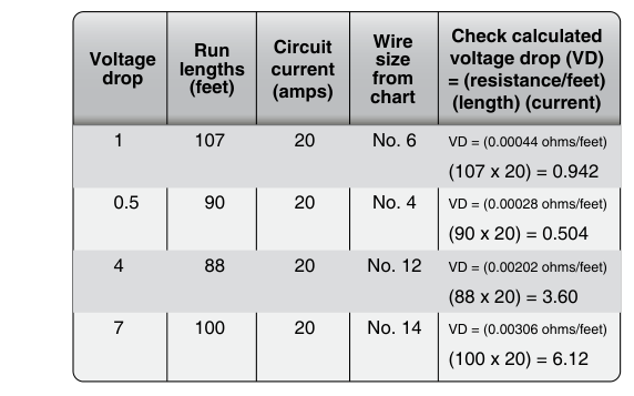
Voltage drop is calculated with the same Ohm's Law relationship. If a circuit carries 10 amperes through a wire that has a total resistance of 0.5 ohms (accounting for the full circuit length, including the return path), the voltage drop in the wire alone is 10 × 0.5 = 5 volts. On a 14-volt aircraft bus, losing 5 volts in the wiring means only 9 volts actually reach the load — far below what most equipment requires. That same wire in a 28-volt system would leave 23 volts at the load, which might be acceptable; this illustrates why voltage drop is always evaluated as a percentage of supply voltage rather than as an absolute number.
Allowable Voltage Drop Limits
FAA guidance, reflected in Advisory Circulars and the principles taught in the Aviation Maintenance Technician Handbook – General (FAA-H-8083-30), establishes maximum allowable voltage drops for aircraft wiring. The generally accepted standard is:
- Continuous-duty circuits (avionics, lighting, instruments): no more than 1 volt drop on a 14-volt system, or 2 volts drop on a 28-volt system.
- Intermittent-duty circuits (starters, solenoids activated briefly): up to 2 volts drop on a 14-volt system, or 4 volts drop on a 28-volt system.
AC 43.13-1B expresses allowable voltage drop as a percentage of source voltage rather than a fixed number of volts common to all bus voltages, with typical published limits on the order of about 2% for single-engine aircraft wiring and about 4% for multi-engine aircraft wiring, depending on the circuit and wiring diagram reference used. Always verify exact values against the specific aircraft manufacturer's data and applicable advisory circular for the aircraft you are working on, as some installations are more stringent.
The Wire Gauge Selection Process
Selecting wire gauge requires balancing two distinct concerns: voltage drop (circuit performance) and current-carrying capacity (ampacity). A wire must satisfy both criteria, and the more conservative (larger) gauge that satisfies both is the correct choice.
Step 1 — Determine the Circuit Current
Identify the maximum current the circuit will carry in normal operation. This is usually stated in the equipment specification or calculated by dividing the load's rated wattage by its supply voltage (P = I × E, rearranged to I = P ÷ E).
Step 2 — Determine Circuit Length
Measure the total wire run from the power source to the load and back to ground. If the aircraft uses a single-wire system with airframe ground return (very common in light aircraft), the length of the ground return path must still be estimated and included, or conservative engineering judgment applied. For a two-wire isolated system, total circuit length is simply the supply wire length plus the return wire length.
Step 3 — Select for Voltage Drop
Using the allowable voltage drop (1 volt or 2 volts, as applicable) and the circuit current, determine the maximum allowable resistance: Rmax = Vdrop ÷ I. Then, using wire resistance tables (which express resistance in ohms per foot or ohms per 1,000 feet for various AWG sizes), find the largest AWG number (smallest wire) whose resistance across the full circuit length stays within Rmax. Resistance tables are published in AC 43.13-1B and in the AMT General handbook.
Step 4 — Check Ampacity
Every wire has a maximum current rating — its ampacity — based on how much heat the insulation can safely tolerate before degradation occurs. Ampacity is affected by whether the wire runs in free air or is bundled with other wires in a conduit or harness (bundling reduces the ability to shed heat, lowering allowable current). The wire selected in Step 3 must have an ampacity rating equal to or greater than the circuit's maximum current. If the chosen wire is too small to handle the current safely, move to the next larger gauge and recheck.
Step 5 — Verify Overcurrent Protection
Circuit breakers and fuses must be sized to protect the wire, not the load. The overcurrent protection device must be rated at or below the wire's ampacity. A wire rated for 15 amperes must never be protected by a 20-ampere breaker; if the wire overheats at 18 amperes, the breaker will not trip in time to prevent damage.
Wire Bundling and Derating
When many wires are bundled together — as they inevitably are in aircraft wiring harnesses — each wire's ability to dissipate heat is reduced because neighboring wires contribute heat of their own. FAA guidance provides derating factors for bundled wires. A wire that can carry 15 amperes in free air might be derated to 11 or 12 amperes when it is part of a large bundle. Always apply the appropriate derating factor from the published table before finalizing wire gauge selection. Failure to derate is a common cause of wiring harness overheating in service.
Why It Matters — Safety and Airworthiness
Voltage drop problems are insidious because the wiring may look perfectly fine on visual inspection. A wire that is one gauge too small may carry current for years before a chafed spot, a higher-than-normal load, or a hot day in a crowded engine compartment finally causes insulation failure. The FAA and the NTSB have identified electrical fires caused by wire degradation as a serious ongoing concern in general aviation.
From an airworthiness perspective, undersized wire that causes excessive voltage drop can also cause avionics to produce erroneous outputs, navigation instruments to read incorrectly, or autopilot servos to operate sluggishly — none of which are acceptable. Getting the gauge right during maintenance or modification is far cheaper and safer than diagnosing mysterious avionics faults after the fact.
Key Numbers and Rules
- AWG scale is inverse: higher AWG number = smaller diameter wire.
- Continuous duty voltage drop limit: 1 volt (14V system) or 2 volts (28V system).
- Intermittent duty voltage drop limit: 2 volts (14V system) or 4 volts (28V system).
- Total circuit length includes both supply and return conductors.
- Overcurrent protection must be rated at or below the wire's ampacity — never above it.
- Bundled wire ampacity is lower than free-air ampacity; apply derating factors from published tables.
- AC 43.13-1B (Acceptable Methods, Techniques, and Practices – Aircraft Inspection and Repair) is the primary FAA reference for aircraft wiring specifications and wire tables.
Common Test Traps
- Confusing AWG direction: Many students assume AWG 22 is heavier than AWG 4 because 22 is a larger number. Remember: higher number, smaller wire.
- Forgetting the return path: Voltage drop calculations must use the total circuit length — wire out plus wire back — not just the one-way distance to the load.
- Using current limits instead of voltage drop limits to size wire: Ampacity is a minimum floor, but the voltage drop calculation often demands a larger gauge. Both criteria must be satisfied; the larger (heavier) gauge wins.
- Sizing the breaker to the load, not the wire: The overcurrent device protects the wire. A 10-ampere load on a 15-ampere-rated wire requires a breaker no larger than 15 amperes, not 10 amperes or 20 amperes.
- Ignoring bundling derating: Wire in a harness bundle cannot carry as much current as the same wire in free air. Neglecting the derating factor and using free-air ampacity tables directly is a common and dangerous mistake.