Gas Tungsten Arc Welding — universally known in the shop as TIG welding — stands as the preferred fusion-welding process for most aircraft structural work. Whether a technician is repairing a chromoly steel engine mount, fabricating a titanium firewall fitting, or joining aluminum control surface skins, GTAW delivers the combination of heat control, cleanliness, and metallurgical integrity that aviation demands. Understanding how the process works, why each parameter matters, and how to avoid the defects that cause parts to fail is fundamental knowledge for any AMT seeking airframe certification or working under an FAA repair station.
The FAA addresses welding standards and inspection criteria primarily in Aviation Maintenance Technician Handbook — Airframe (FAA-H-8083-31), Chapter 5, which covers welding processes, acceptable weld quality, and material-specific considerations for certificated aircraft structures. Every technique described in this article is grounded in that guidance.
How GTAW Works
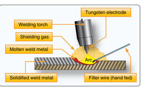
TIG welding creates a welding arc between a non-consumable tungsten electrode and the base metal. Unlike MIG (GMAW), the electrode does not melt into the weld pool. Instead, filler metal is introduced manually by dipping a separate filler rod into the leading edge of the molten puddle — a skill that separates competent TIG welders from beginners. The entire weld zone is blanketed by a flow of inert shielding gas, typically pure argon or an argon-helium blend, which prevents atmospheric oxygen and nitrogen from contaminating the hot metal.
The power source for GTAW is a constant-current (CC) machine that can supply either Direct Current Electrode Negative (DCEN) or Alternating Current (AC). The choice is dictated by the base metal being welded:
- DCEN (straight polarity): Used for steel, stainless steel, titanium, and most ferrous aircraft structures. Most of the arc heat is concentrated at the base metal, producing a deep, narrow fusion zone with minimal heat input into the surrounding structure — critical when working near heat-treated components.
- AC: Required for aluminum and magnesium alloys. The alternating polarity creates a surface-cleaning action called cathodic cleaning on the electrode-positive half-cycle, which breaks up and removes the refractory aluminum oxide layer that otherwise prevents fusion. Without cathodic cleaning, the oxide acts as a barrier and the weld simply will not fuse properly.
Equipment and Setup
A TIG torch holds the tungsten electrode in a collet and channels shielding gas through a ceramic or glass cup surrounding the electrode tip. Torch selection matters: water-cooled torches handle higher amperages and sustained work cycles common in production shops, while air-cooled torches are lighter and more maneuverable for delicate fuselage or airframe repairs.
Tungsten electrode selection is equally important. For DCEN on steel and titanium, pure thoriated or ceriated tungsten electrodes are used and are ground to a sharp point, which concentrates the arc and gives the welder directional control. For AC aluminum welding, a pure or zirconiated tungsten is typically used, and the tip is allowed to form a small hemispherical ball during welding — this ball shape is normal and desirable, stabilizing the arc during polarity reversals. The electrode diameter must be matched to the amperage range: too small an electrode at high current will contaminate the weld with tungsten inclusions; too large an electrode at low current produces an unstable arc.
High-frequency (HF) arc starting is standard on modern GTAW machines. HF allows the arc to be initiated without touching the tungsten to the base metal, which prevents tungsten contamination of the weld and pitting of the base metal — both unacceptable in aircraft work. Scratch-start is never used on certificated aircraft structural welds for this reason.
Technique: The Welder's Hands and Movement
Proficient GTAW requires coordinating three independent motions simultaneously: maintaining a consistent electrode-to-work distance (arc length), moving the torch along the joint at a steady travel speed, and feeding filler rod into the puddle at the correct rate and angle. Most aircraft welding is done with the torch held at approximately 15–20 degrees from vertical (trailing angle) and the filler rod introduced at a low angle, roughly 15 degrees from the base metal surface, on the opposite side of the puddle from the direction of travel.
The filler rod must be dipped into the leading edge of the molten pool — never held in the arc or touched to the tungsten. Touching the filler rod to the tungsten electrode is one of the most common beginner errors; it immediately contaminates both the tungsten and the weld pool with oxides, requiring the electrode to be reground and the contaminated area of weld to be ground out and rewelded.
Travel speed must be matched to heat input. Too slow, and the heat-affected zone (HAZ) grows excessively large, potentially annealing hardened components or causing distortion in thin sheet. Too fast, and the weld bead becomes narrow and convex with poor fusion at the toes. On thin-gauge aircraft tubing — such as 4130 chromoly fuselage members — the welder typically uses a series of tack welds spaced around the joint before running continuous beads, alternating sides to distribute and minimize heat distortion.
Material-Specific Considerations
4130 Chromoly Steel
Chrome-molybdenum steel (4130) is the backbone of welded steel aircraft structures — engine mounts, fuselage frames, and landing gear components. For GTAW on 4130, ER70S-2 or ER80S-D2 filler rods are commonly used. Preheating thicker sections is a recognized good practice to help prevent hydrogen cracking and reduce thermal shock, with the specific temperature and thickness threshold varying by section thickness and application per manufacturer or engineering data. After welding, slow cooling — sometimes assisted by wrapping the assembly in an insulating blanket — helps minimize residual stress. The as-welded zone in 4130 is softer than the parent metal; normalization or stress relief heat treatment may be required per the manufacturer's data before return to service.
Aluminum Alloys
Aluminum presents two unique challenges: its high thermal conductivity rapidly pulls heat away from the weld zone (making fusion difficult) and its oxide layer melts at a much higher temperature than the base aluminum itself. AC GTAW addresses both: the cathodic cleaning action removes oxide, and the welder compensates for conductivity by using higher amperage than would be expected for the material thickness. Common filler alloys include 4043 (general purpose, good fluidity) and 5356 (higher strength, commonly used where greater joint strength is needed); the choice between them depends on the specific alloy being joined, strength requirements, and the service environment rather than a blanket corrosion-resistance advantage. Cleanliness is non-negotiable: base metal and filler must be cleaned with acetone and a dedicated stainless steel brush immediately before welding. Any grease, moisture, or oxide contamination left on the surface will be trapped in the weld and produce porosity.
Titanium
Titanium's sensitivity to contamination at elevated temperatures makes it the most demanding aircraft welding task. As temperatures climb into the several-hundred-degree range and beyond, titanium becomes increasingly reactive with oxygen, nitrogen, and hydrogen in the atmosphere, producing brittle surface discoloration — a reliable quality indicator. A properly welded titanium joint should display a bright silver to light straw color; blue, purple, gray, or white oxidation indicates inadequate shielding and the weld must be rejected. Trailing shields and backing bars that flow argon over the back side of the joint are mandatory. The work area must be meticulously clean and draft-free.
Weld Quality and Inspection
FAA-H-8083-31 defines the visual characteristics of an acceptable aircraft weld. A good TIG weld on steel tubing or sheet should be smooth, uniform in width and height, with a consistent ripple pattern. The weld toes must blend smoothly into the base metal with no undercut — a groove melted into the base metal at the edge of the weld — which acts as a stress riser and fatigue initiation site. Cracks, porosity, overlap, and incomplete fusion are cause for rejection and repair. Weld reinforcement (crown height) should be present but not excessive; a flat or slightly convex crown is acceptable, while a very high, narrow bead indicates too little heat or travel speed.
Key Numbers and Rules
- Shielding gas: Welding-grade pure argon for most aircraft GTAW; argon-helium blends increase heat input for thick aluminum sections.
- Electrode type: Pointed thoriated/ceriated tungsten for DCEN (steel, titanium); pure or zirconiated for AC (aluminum).
- Acceptable weld color — titanium: Silver to light straw = acceptable; blue, purple, gray, or white = reject.
- 4130 preheat: Preheating thicker sections is good practice to reduce hydrogen cracking risk and thermal shock; exact temperature and thickness thresholds should follow manufacturer or engineering data rather than a single fixed rule.
- Arc starting: High-frequency (HF) non-contact start required; scratch-start is prohibited on aircraft structural welds.
- Filler rod handling: Never allow the filler rod to contact the tungsten or be held in the arc stream; always dip into the leading edge of the puddle.
Common Test Traps
- Polarity confusion: The FAA exam frequently tests whether candidates know that AC is required for aluminum GTAW, not DCEN. DCEN does not provide cathodic cleaning and will not break through the aluminum oxide layer.
- Tungsten tip shape: Students often assume all tungsten electrodes should be pointed. For AC aluminum welding, the balled tip is correct — a pointed tip on AC current is unstable and incorrect.
- Titanium color acceptance: Straw-yellow coloring on titanium welds is acceptable; any blue or darker shade indicates contamination. Exam questions may try to trick you into rejecting a straw-colored weld.
- Filler rod contamination: Touching the filler to the tungsten electrode or leaving it in the arc stream does not merely reduce weld quality slightly — it contaminates both the tungsten and the pool with oxides, requiring rejection and rework of that weld area.
- Undercut vs. overlap: Undercut is a groove at the weld toe (always a reject condition on aircraft work); overlap is filler metal that rolled over the toe without fusing. Both are rejectable, but students sometimes confuse which defect is which on visual inspection questions.