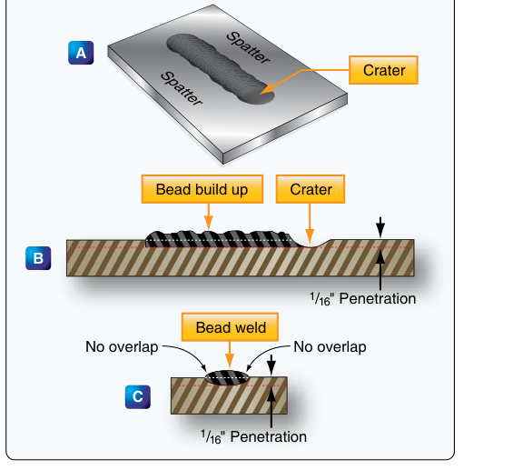
In aircraft welding, the finished weld bead is more than a seam — it is a visual and structural record of every decision the welder made: heat input, travel speed, filler rod technique, joint preparation, and shielding gas coverage. For the Aviation Maintenance Technician (AMT) working on airframes, the ability to evaluate weld bead quality is not optional. The FAA requires that all welded structure meet airworthiness standards, and the first line of inspection is almost always a careful visual examination of the bead itself. Understanding what a good bead looks like, what defects look like, and why those defects form gives the technician both the diagnostic skill to reject bad work and the knowledge to avoid producing it in the first place.
This article covers weld bead characteristics as described in FAA maintenance guidance, focusing on the oxyacetylene and gas tungsten arc welding (GTAW/TIG) processes most commonly used on steel and aluminum airframe tubing and sheet structure.
What a Quality Weld Bead Looks Like
A structurally acceptable aircraft weld bead has several hallmarks that are consistent regardless of the welding process. When you inspect a properly executed bead, you should see the following characteristics working together:
- Uniform width and height: The bead should maintain a consistent width from start to finish, with gentle, even ripples that indicate a steady travel speed and consistent heat input. Width variation signals that the welder's speed or heat changed unpredictably.
- Smooth, uniform ripple pattern: The ripples in the bead surface are formed by the progression of the weld pool. Evenly spaced ripples with a consistent arc indicate controlled technique. Irregular spacing or abrupt changes in ripple shape suggest travel-speed fluctuations or an inconsistent torch angle.
- Proper reinforcement (crown height): The bead should be built up slightly above the surface of the base metal, providing added cross-sectional area without creating a stress concentration. A bead that is too flat (underfilled) leaves the joint weakened; a bead that is excessively high creates a sharp notch at the toe of the weld, which concentrates stress under vibration loads.
- Good fusion at the toes: The toes of the weld — the edges where the bead meets the base metal — should blend smoothly and gradually into the surrounding material. There should be no sharp groove, undercut, or abrupt step. Smooth toes indicate full fusion down to the root of the joint.
- Consistent color: On chrome-moly (4130) steel tubing welded with oxyacetylene or TIG, the weld and the adjacent heat-affected zone (HAZ) should display a straw or light blue oxide color immediately after welding, indicating the metal was protected from excessive oxidation. A gray or white chalky appearance may indicate inadequate shielding or contamination. Aluminum GTAW beads should appear bright and silvery when properly shielded.
- No visible surface defects: The surface of the bead should be free of cracks, porosity pits, craters, or inclusions visible to the naked eye.
Common Weld Defects and Their Causes
The FAA Aviation Maintenance Handbook references several categories of weld defects that render a joint unairworthy. Knowing each defect's appearance, cause, and structural consequence is essential for both inspection and prevention.
Porosity
Porosity appears as small pits or holes on or just below the surface of the bead. It is caused by gas becoming trapped in the weld pool as it solidifies. Typical causes include contamination of the base metal (oil, moisture, rust, paint) and inadequate shielding gas coverage; an excessively high shielding gas flow rate can also create turbulence that draws in atmospheric air, though this is a less commonly cited cause than contamination or insufficient coverage. Even subsurface (internal) porosity that is not visible externally can significantly reduce joint strength by creating internal voids where cracks can initiate under cyclic loading.
Undercut
Undercut is a groove melted into the base metal at the toe of the weld that is not filled by weld metal. It appears as a channel or depression running along one or both sides of the bead. Undercut is caused by excessive heat, too high a welding current (on TIG), or an improper torch angle that directs heat away from the joint and into the base metal at the toe. Undercut is particularly dangerous on airframe structure because it creates a notch — a geometric stress riser — exactly at the location where the bead transitions to the base metal, where bending and fatigue stresses are already highest.
Incomplete Fusion (Cold Lap)
Incomplete fusion, sometimes called cold lap, occurs when the weld metal does not fully bond to the base metal or to a previous weld pass. The bead may look acceptable on the surface but is not metallurgically joined below. This happens when heat input is insufficient, travel speed is too fast, or the joint is not properly cleaned and prepared. Incomplete fusion produces a joint that may pass visual inspection but carries a hidden interface crack, making it especially dangerous.
Cracks
Cracks may appear in the weld metal itself (hot cracks, which form during solidification) or in the HAZ (cold cracks, which can form after welding, generally associated with residual stress and, in certain steel welding processes, hydrogen-induced cracking). Hot cracks often run along the centerline of the bead. Cold cracks in the HAZ may be nearly invisible without magnification. Any crack in an airframe weld is cause for rejection — cracks propagate under vibration and fatigue loading and can lead to catastrophic structural failure.
Overlap (Cold Overlap)
Overlap occurs when the weld metal rolls over the base metal at the toe without actually fusing to it. It creates a mechanically locked but not bonded interface and results in a sharp notch at the unmixed boundary. Like undercut, overlap concentrates stress; like incomplete fusion, the boundary is a latent crack initiation site.
Excessive Spatter
In arc welding processes, excessive spatter — small droplets of weld metal deposited around the bead — indicates too high a current, incorrect polarity, or contaminated wire. While spatter itself may not weaken the joint directly, its presence suggests process control problems that likely produced internal defects as well. Spatter on tubing also creates stress concentration points if not removed.
Crater Cracks
At the end of a weld, if the arc or flame is extinguished too abruptly, a concave depression called a crater forms. Craters are prone to cracking because the last metal to solidify shrinks and has no surrounding liquid metal to draw from. Proper technique requires filling the crater before terminating the weld, using a back-step or post-weld fill technique.
Why Weld Quality Matters on Airframes
Aircraft welded structure — particularly steel tube fuselage frames, engine mounts, and control system components — operates under complex, cyclically varying loads that include tension, compression, bending, torsion, and vibration. Unlike a static structure, an airframe weld must perform reliably across thousands of flight hours without degradation. Fatigue failure is the dominant failure mode, and fatigue cracks almost always initiate at stress concentrations. Every defect listed above — undercut, porosity, overlap, cracks — is a stress concentration. This is why the FAA and industry standards demand that aircraft welds be visually and, when required, non-destructively inspected before returning structure to service. A weld that would be acceptable in a farm implement may be unairworthy in a primary flight structure component.
Key Numbers and Inspection Rules
- Crown height: Weld reinforcement should be built up slightly above the base metal surface; excessive buildup creates a stress riser at the toe.
- Undercut depth: Any undercut on primary structure is typically cause for rejection; minor undercut on secondary structure must not reduce the effective throat of the joint.
- Visual inspection first: FAA guidance specifies that visual inspection is the primary method for weld quality assessment on airframe tube and sheet structure.
- Non-destructive testing (NDT): Dye penetrant inspection (DPI) is commonly used to reveal surface cracks and porosity not visible to the naked eye. Radiographic (X-ray) inspection may be used for critical or complex joints to reveal internal defects.
- Base metal condition: The weld area must be clean, free of scale, paint, oil, and moisture before welding — contamination is the leading cause of porosity.
- Weld color on 4130 steel: A straw to light blue HAZ color is acceptable; gray or white scale indicates oxidation from poor gas coverage or flame adjustment.
Common Test Traps
- Confusing undercut with overlap: Undercut is metal removed (a groove) from the base metal at the toe; overlap is weld metal deposited over but not fused to the base metal. Both are defects, but they look and form differently.
- Assuming a smooth bead surface means a good weld: Incomplete fusion and internal porosity can produce a visually clean bead. Surface appearance alone is not sufficient for critical joints — NDT may be required.
- Misidentifying crater cracks: A crater at the weld termination point is not automatically a defect if it is filled; an unfilled crater that has cracked is a rejectable condition.
- Thinking spatter is purely cosmetic: Spatter on tube structure creates stress concentrations and also signals improper welding parameters that likely produced worse internal problems.
- Overlooking the heat-affected zone: Inspection must include the HAZ adjacent to the bead, not just the bead itself. Cold cracks and grain growth in the HAZ can be as structurally significant as defects in the weld metal.