Welding is one of the most demanding skills in aircraft maintenance, and even a technically perfect welding technique can produce a dangerously weak joint if the underlying joint design or part fit-up is inadequate. In aircraft structures, where weight and strength must be carefully balanced and every joint is potentially safety-critical, the design of a weld joint — its geometry, preparation, and pre-weld alignment — is just as important as the welder's hand skill. The FAA's Aviation Maintenance Technician Handbook — Airframe (FAA-H-8083-31) dedicates significant attention to joint design precisely because these decisions are made before the arc is ever struck or the torch is lit.
This article walks through the major weld joint types used in aircraft, the factors that govern joint selection, what good and bad fit-up look like, and the practical steps an AMT must take to prepare parts correctly before welding. A thorough understanding of these principles is essential for both the FAA AMT Knowledge Test and real-world airframe repair work.
The Five Basic Weld Joint Types
All weld joints in aircraft — whether made by gas welding or TIG — fall into one of five fundamental categories. Each has distinct mechanical characteristics and applications:
- Butt Joint: Two pieces of material are placed edge to edge in the same plane. This is the most straightforward joint for joining sheet metal or tube ends. When properly prepared and welded, a butt joint allows stress to flow in a direct, uncomplicated path. For thin aircraft sheet, a butt joint may require no special edge preparation; for thicker material, beveling one or both edges (creating a V-groove, J-groove, or U-groove) is necessary to ensure full penetration.
- Corner Joint: Two pieces meet at roughly a right angle, forming an outside corner. Common in box structures, frames, and skin-to-frame connections. A corner joint can be welded on the outside of the corner, the inside (forming a fillet), or both, depending on loading requirements and accessibility.
- T-Joint: One piece of metal is welded perpendicular to the surface of another, forming a T-shape. Aircraft bulkhead attachments and tube cluster connections are practical examples. T-joints are typically welded with fillet welds on one or both sides. Because the load must transfer through the fillet, T-joints are generally not as efficient as butt joints under tension but are excellent in shear.
- Lap Joint: Two pieces overlap, and a weld is placed along the edge or edges of the overlap. Lap joints are convenient when sheet metal must be joined without close edge preparation, but they introduce stress concentrations at the weld toes and add weight from the overlapping material. In primary aircraft structure, lap joints are used conservatively.
- Edge Joint: Two or more parallel pieces are welded along their coinciding edges. Edge joints are mainly used on non-structural or lightly loaded applications such as flanges or sheet metal seams. They are not suitable for primary structural welds because they offer limited strength under tension or bending loads.
Groove Weld Preparations
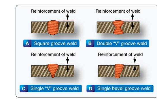
For butt joints in material thicker than about 3/16 inch, a flat, square edge cannot be welded to full penetration without special preparation. Groove preparations are edge geometries that open a channel for the weld metal to penetrate through the full thickness of both parts. Common groove types include:
- Square groove: No bevel — used for thin material where full penetration is achievable with a single pass.
- Single-V groove: Both edges are beveled to form a V. The included angle and root face dimensions depend on material thickness and process and should follow the applicable repair drawing or structural repair manual rather than a single fixed value. A small root face (the flat land at the bottom of the bevel) is left, as specified by the repair drawing, to help prevent burn-through at the root.
- Double-V groove: Bevels on both sides, used on thicker material to reduce the volume of weld metal required and to balance distortion on both faces.
- J-groove and U-groove: More complex curved preparations that reduce weld metal volume compared to V-grooves; used less frequently in general airframe repair but found in highly engineered components.
Incorrect groove angle is a common source of defects. Too narrow a groove prevents adequate electrode or filler rod manipulation, leading to lack of fusion. Too wide a groove wastes filler metal, increases heat input, and promotes distortion.
Root Opening and Root Face
Two critical fit-up dimensions govern how the root of a groove weld is made: the root opening and the root face. The root opening is the gap deliberately left between the two pieces before welding. A small, consistent root opening — as specified on the repair drawing — ensures that weld metal fully penetrates to the back side of the joint. Too large a root opening causes burn-through and excessive weld metal consumption; too small a root opening causes incomplete penetration, the most serious and common defect in structural welds.
The root face is the small, flat, un-beveled portion of the edge left at the base of the groove. It prevents the heat of welding from burning completely through the part at the very start of the weld pool. Together, the root opening and root face are set as a matched pair, per the repair drawing or SRM: as root face increases, root opening may also need to increase slightly to maintain full penetration.
Fillet Weld Geometry
Fillet welds — the triangular cross-section welds used in T-joints, lap joints, and corner joints — are specified by their leg size and evaluated by their throat. The theoretical throat of a fillet weld is the distance from the root of the joint to the hypotenuse of the weld cross-section triangle. For a 45-degree equal-leg fillet, the throat equals 0.707 times the leg size. The throat is the thinnest cross-section through which shear stress passes, so it directly governs fillet weld strength. Aircraft repair data will specify a minimum fillet weld leg size; meeting or slightly exceeding that size is correct, while significantly oversized fillets add unnecessary weight and heat stress to the surrounding structure.
Fit-Up: The Foundation of Weld Quality
Fit-up refers to how accurately the parts are positioned, aligned, and held in place before welding begins. Poor fit-up is the leading cause of weld defects in aircraft repair work. Critical fit-up parameters include:
- Alignment: Mating surfaces must be properly aligned so that no angular or linear offset (mismatch) exists. Even a small offset in a butt weld creates a stress riser that dramatically reduces fatigue life.
- Gap consistency: The root opening must be uniform along the entire length of the joint. Taper in the gap causes the welder to fight changing burn-through risk and penetration depth throughout the pass.
- Surface cleanliness: All oil, paint, mill scale, oxide, moisture, and corrosion must be removed from the joint area before welding. These contaminants cause porosity, inclusions, and lack of fusion. On chromoly steel (4130), a light pass with a clean stainless steel wire brush immediately before welding is standard practice.
- Tack welds: Properly placed tack welds hold parts in position during welding. Tacks must be strong enough to resist the distortion forces of welding but small enough to be fully remelted and absorbed into the final weld. Placing tacks too close together prevents the welder from working freely; too few tacks allow the joint to open or close as heat is applied.
- Fixturing: Jigs and fixtures hold parts in precise alignment, especially important for tubular fuselage structures where multiple joints meet at a cluster. Fixtures also allow the welder to position the work favorably, which is critical since out-of-position welding (vertical, overhead) is significantly more difficult and more prone to defects.
Why Joint Design and Fit-Up Matter for Airworthiness
Aircraft structures endure repeated loading cycles, vibration, and in some cases, significant dynamic stress. A weld that looks acceptable on the surface but has an internal lack-of-fusion defect, incomplete penetration, or a stress-concentrating misalignment may pass a visual inspection but fail in fatigue at a fraction of its design life. The FAA and aircraft manufacturers specify joint designs precisely because the geometry of the joint controls how stress is distributed. Changing a joint type, reducing groove angle, or accepting poor fit-up without engineering authority can render a repair non-airworthy even if the welding itself is flawless by visual standards.
Key Numbers and Rules
- Single-V groove included angle and root face dimensions: set by the applicable repair drawing or structural repair manual, not a single fixed handbook value.
- Theoretical throat of an equal-leg fillet weld: 0.707 × leg size.
- Material thickness above which groove preparation is generally required: approximately 3/16 inch for butt joints.
- Surface prep: remove all contaminants (oil, paint, oxide, and dirt) from the joint area and adjacent base metal before welding, per the applicable repair data.
- Always weld to an approved data source (manufacturer's structural repair manual, FAA-approved repair drawing, or AC 43.13-1B) — joint design cannot be changed without engineering approval.
Common Test Traps
- Confusing throat and leg: The FAA test may ask about fillet weld strength in terms of throat, not leg. Remember that throat = 0.707 × leg for a standard equal-leg fillet — the throat is always less than the leg size.
- Root opening vs. root face: These are two separate dimensions that work together. The test may describe a scenario where both are zero — this means a square groove with parts pressed tightly together, which increases the risk of incomplete penetration in material thicker than about 3/16 inch, where groove preparation is generally required.
- Lap joint limitations: Students often assume lap joints are strong because they look sturdy. The FAA expects you to know that lap joints create stress concentrations and are generally unsuitable for primary structure under tension loading.
- Cleanliness requirements: A common distractor is that only the weld line itself needs cleaning. In reality, the base metal on both sides of the joint must be cleaned to prevent contamination from migrating into the weld pool.
- Tack weld placement: Placing tack welds only at the ends of a joint (rather than at intervals along its length) is a common error. Insufficient tacking allows joint distortion during welding, which changes fit-up mid-weld and produces an irregular final bead.