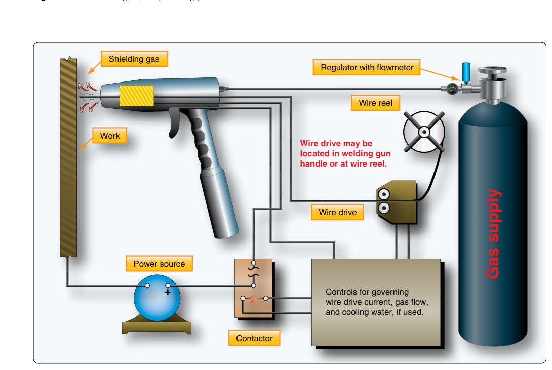
Gas Metal Arc Welding — universally known in the shop as MIG welding (Metal Inert Gas) — is one of the most efficient arc welding processes available to aviation maintenance technicians. Formally designated GMAW (Gas Metal Arc Welding) by the American Welding Society, the process feeds a continuous solid wire electrode through a handheld gun while simultaneously flooding the weld zone with a shielding gas that keeps atmospheric oxygen and nitrogen away from the molten metal. The result is a clean, mechanically sound weld that can be deposited much faster than traditional TIG or oxy-acetylene processes. For the AMT Airframe candidate, understanding GMAW means understanding not just the hardware but also its limitations, the metals it can join on certified aircraft, and the inspection criteria that determine whether a finished weld is airworthy.
The FAA's Aviation Maintenance Technician Handbook — Airframe (FAA-H-8083-31) dedicates considerable attention to welding processes used in airframe repair. While GMAW is not the dominant process for thin-gauge aircraft steel tubing (TIG and oxy-acetylene still reign there), it has legitimate and growing applications in airframe sheet metal repair, structural component fabrication, and the repair of heavier-section steel and aluminum assemblies. Knowing when GMAW is appropriate — and when it is not — is a core competency for the certificated airframe technician.
How GMAW Works
In GMAW, an electric arc is struck between the continuously fed wire electrode and the base metal. The wire is stored on a spool inside the welding machine and driven by a motorized feed mechanism through a flexible conduit to the gun. As the wire melts into the weld pool, it is simultaneously replaced by fresh wire from the spool, so the welder never has to stop and change an electrode. This is the fundamental advantage of GMAW over Shielded Metal Arc Welding (SMAW, or stick welding): continuous deposition without interruption.
The shielding gas flows concentrically around the wire through the nozzle of the gun, blanketing the arc and molten puddle. Common shielding gases used in aircraft work include:
- Pure Argon: preferred for aluminum welding; argon's heavier-than-air weight helps it settle over the weld pool and provides excellent arc stability on nonferrous metals.
- 75% Argon / 25% CO₂ (C25): a popular mix for mild and low-alloy steel; the CO₂ adds penetration and arc energy while the argon stabilizes the arc and reduces spatter.
- Pure CO₂: produces deeper penetration on steel but generates more spatter and a less stable arc; used industrially but less common in precision aircraft work.
- Argon-Helium blends: used for specialty applications such as welding thicker aluminum sections; helium raises arc energy and improves fusion.
The welding machine itself is a constant-voltage (CV) power source. Unlike a constant-current machine (typical of TIG), a CV machine maintains a relatively stable output voltage regardless of small changes in arc length. When the arc length shortens slightly and arc resistance drops, the machine automatically increases current to burn back the wire, self-regulating the arc. This self-correcting behavior is one reason GMAW is faster to learn than TIG.
Transfer Modes
The way molten metal moves from the wire to the weld pool depends on voltage, wire feed speed, and shielding gas. Three primary transfer modes apply in aircraft shop practice:
- Short-Circuit Transfer (Short-Arc): occurs at low voltage and wire feed speeds. The wire physically touches the puddle, short-circuits, melts off, and re-establishes the arc in rapid succession — up to 200 times per second. This produces a small, controllable puddle with low heat input, making it ideal for thin sheet metal and out-of-position welds. It is the most commonly used GMAW mode in airframe repair.
- Globular Transfer: a transitional mode between short-circuit and spray; metal transfers in large, irregular drops. It tends to generate spatter and is generally avoided in precision aircraft work.
- Spray Transfer: at higher voltage and current, metal is propelled across the arc in a fine, continuous spray of tiny droplets. It produces excellent fusion and a smooth bead, but the high heat input requires flat-position welding and thicker base metal. Spray transfer is useful for heavier structural steel components but unsuitable for thin-gauge tubing.
Applications in Aircraft Airframe Repair
The FAA-H-8083-31 handbook identifies several areas where GMAW is appropriately applied in airframe work. The technician must always verify that the aircraft manufacturer's maintenance manual or an FAA-approved data source authorizes a particular welding process before proceeding.
- Steel sheet metal repairs: Low-alloy steel skins, firewalls, and engine mounts can be MIG welded using appropriate filler wire. 4130 chromoly steel, a common airframe material, is routinely MIG welded with ER80S-D2 or ER70S-2 filler wire, though the technician must be mindful of heat-affected zone (HAZ) effects on the material's mechanical properties.
- Aluminum sheet metal: GMAW with pure argon shielding and ER4043 or ER5356 aluminum filler wire is used on aluminum skin repairs and structural components. The process is faster than TIG for longer aluminum welds and handles thicker aluminum sections effectively. However, TIG (GTAW) generally remains preferred for thin aluminum due to its superior heat control.
- Fabrication of non-critical steel assemblies: Brackets, racks, and cargo structure fabricated from mild or low-alloy steel are common GMAW applications.
- Heavier tubing and fittings: Where wall thickness is sufficient to tolerate the higher heat input of spray-transfer GMAW, the process can be applied to structural steel tube assemblies per approved data.
Critically, GMAW is generally not recommended for welding very thin-gauge chromoly tubing (such as 0.035-inch or 0.049-inch wall thickness fuselage and wing strut tubing) found in traditional steel tube-and-fabric aircraft. The heat input control of GMAW is inferior to TIG for these applications, and burn-through risk is significant. Oxy-acetylene or GTAW (TIG) remains the process of choice for such work.
Equipment Setup and Safety
Proper machine setup is essential for weld quality and safety. The technician must select wire diameter appropriate to the base metal thickness, set voltage and wire feed speed to achieve the correct transfer mode, and verify shielding gas flow rate (typically 15–25 cubic feet per hour for most aircraft applications). Gun angle — both work angle and travel angle — affects bead profile and fusion. A slight push angle (gun tilted 5–15° in the direction of travel) is typical for GMAW; it produces a flatter bead and allows better visibility of the leading edge of the puddle.
GMAW generates intense ultraviolet and infrared radiation; a welding helmet with the appropriate shade lens (commonly shade 10 for GMAW) is mandatory. Fire-resistant gloves, a leather welding jacket, and respiratory protection from fumes are standard personal protective equipment. The shop must be well-ventilated, and welding near aircraft fuel systems or flammable materials requires strict fire watch procedures per shop safety policy.
Weld Inspection and Acceptance Criteria
A completed GMAW weld on an aircraft structure must meet the acceptance criteria outlined in the applicable maintenance manual or FAA advisory circular. The FAA-H-8083-31 handbook describes the visual characteristics of a sound weld versus a defective one. Acceptable welds display uniform bead width and height, smooth ripple pattern, complete fusion at the toes of the weld (where the bead meets the base metal), and freedom from cracks, porosity, undercut, overlap, and incomplete fusion.
- Porosity: gas pockets trapped in the solidified weld, usually caused by contaminated base metal, moisture in the shielding gas system, or inadequate gas coverage.
- Undercut: a groove melted into the base metal at the weld toe that is not filled by weld metal; weakens the effective cross-section.
- Overlap (Cold Lap): weld metal that flows over the base metal surface without fusing to it; a stress concentrator.
- Incomplete Fusion: weld metal that did not bond to the base metal or a previous weld pass; a serious structural defect.
- Cracking: hot cracking (solidification cracking) or cold cracking (hydrogen-induced) are cause for rejection and investigation of root cause.
Non-destructive testing methods such as dye-penetrant inspection and radiographic (X-ray) inspection may be required by the maintenance manual for critical structural welds, and the technician must follow approved procedures when performing or witnessing such inspections.
Key Numbers and Rules
- Shielding gas flow rate: typically 15–25 CFH for most GMAW aircraft applications; increase at the higher end for out-of-position or drafty conditions.
- Common steel filler wires: ER70S-2 (versatile, triple-deoxidized, good for contaminated base metal) and ER80S-D2 (higher strength, preferred for 4130 chromoly).
- Common aluminum filler wires: ER4043 (good fluidity, crack-resistant, lower strength) and ER5356 (higher strength, used where the weld must match base metal strength of 5xxx-series alloys).
- Lens shade for GMAW: shade 10 is the typical minimum; higher shades may be required at higher amperages.
- Wire diameter selection: 0.023–0.030 inch wire for thin sheet metal; 0.035 inch and above for heavier sections.
- All welding repairs on certificated aircraft must be performed per FAA-approved data — aircraft maintenance manual, Structural Repair Manual, or FAA-accepted engineering order. Process substitution (using GMAW where the manual calls for GTAW) requires appropriate approval.
Common Test Traps
- Calling MIG and TIG interchangeable: The FAA knowledge test distinguishes between GMAW (continuous wire, constant-voltage machine, shielding gas) and GTAW (non-consumable tungsten electrode, constant-current machine, filler rod fed by hand). They are not interchangeable on the test or in the shop.
- Assuming GMAW is always the best choice for aircraft steel tubing: Thin-wall chromoly fuselage tubing is a poor candidate for GMAW due to heat input concerns; GTAW or oxy-acetylene are preferred for such applications.
- Confusing shielding gas selection: Pure argon is correct for aluminum GMAW; argon-CO₂ mixes are used for steel. Using CO₂-heavy mixes on aluminum produces a poor arc and excessive oxidation.
- Overlooking the need for FAA-approved data: A technician cannot simply decide to MIG weld a structural component because it seems faster. The maintenance manual or other approved data must authorize the process for that specific repair.
- Misidentifying weld defects: Undercut and overlap are commonly confused on written tests. Undercut is a groove in the base metal at the weld edge (too much heat or speed); overlap is weld metal that rolled over without fusing (too little heat or travel speed).