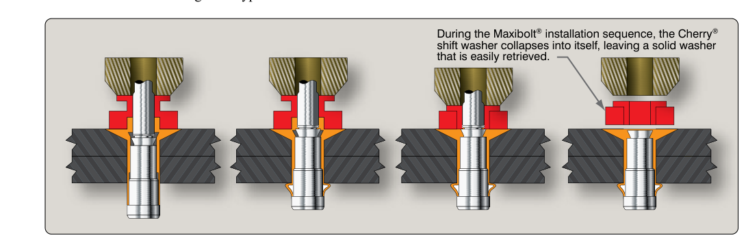
In aircraft sheet metal work, the ideal fastener is a solid shank rivet driven with a bucking bar on the back side — but in the real world, many structural locations simply do not allow access to both sides of the material. Wing skins over sealed ribs, fuselage doublers behind interior panels, and repaired control surface skins may all present this challenge. Blind rivets — fasteners that can be installed and set entirely from one side of the material — were developed specifically for these situations. Understanding their designs, material ratings, installation procedures, and limitations is not only essential for the FAA Airframe Knowledge Test but is a genuine safety matter: a misapplied blind rivet in a primary structure can be a hidden failure waiting to happen.
This article covers the major blind rivet families approved for aircraft use, how each installation mechanism works, the inspection criteria that confirm a good pull, and the practical rules governing where each type may and may not be used.
Why Blind Rivets Are Necessary
Many aircraft assemblies are built in a sequence that permanently encloses interior structure before the outer skin is attached. When damage later requires fastener replacement or the addition of repair doublers in those enclosed areas, there is no way to insert a bucking bar. Blind rivets solve this by completing the entire clamping and heading operation from a single side — the accessible (shop) side — while a mechanical or self-contained mechanism forms a shop head inside the blind cavity. The result, when correctly installed, provides a shear and tension load path similar in principle to a solid shank rivet, though with important differences in strength ratings that dictate their approved applications.
Major Blind Rivet Types Used in Aviation
Pull-Type (Mechanically Locked Stem) Rivets
The most common aviation blind rivet is the pull-type rivet, often called a pop rivet in casual usage, though that term should be avoided on approved repairs because it is associated with the cheapest commercial hardware. The aircraft-grade version consists of a hollow rivet body and a hardened stem (mandrel) that passes through the center. The installation tool grips the protruding stem and pulls it toward the operator while the tool nose pushes against the manufactured head. This action draws the blind end of the rivet body outward and radially, forming a shop head against the far side of the material stack. At a precisely calibrated point, the stem breaks at a pre-engineered breakpoint, leaving a portion of the stem locked inside the rivet body.
The retained stem is critical. On aircraft-approved pull-type rivets such as the MS20600 series (self-plugging, mechanically locked stem rivets, sometimes referred to by trade names such as Cherrylock, along with related specifications like NAS1398/NAS1399), the stem must be locked or retained — a stem that falls out into an airframe is a loose object and a potential foreign object damage (FOD) hazard. Some designs use a mechanical locking collar to positively lock the stem; these are called mechanically locked stem rivets and provide superior vibration resistance and higher allowable loads compared to friction-only stem retention.
Self-Plugging Friction-Lock Rivets
An older and simpler design, the self-plugging friction-lock rivet relies on the stem breaking flush and remaining in the rivet body by friction alone. These are not approved for primary structural applications in most modern aircraft repair data because vibration can work the stem loose over time, reducing the rivet's shear area and creating a FOD source. The Aviation Maintenance Technician Handbook – Airframe (FAA-H-8083-31) specifically notes that friction-lock blind rivets are restricted to non-structural and secondary applications unless an approved Structural Repair Manual (SRM) explicitly calls them out for a specific location.
Bulbed or Structural Blind Rivets
For applications requiring strength approaching that of solid shank rivets, structural blind rivets such as the Huck BOM (Blind Olympic Mount) style fasteners are used. These typically feature thicker rivet bodies, a large formed bulb on the blind side that spreads clamp load over a wider area (reducing bearing stress on the material), and a positive mechanical stem lock. Because the blind-side head is large and well-formed, these rivets tolerate some variation in grip length (material thickness) better than standard pull-type designs. Note that Hi-Lok fasteners, though sometimes grouped with high-strength special fasteners in structural repairs, are a separate two-piece threaded pin-and-collar system requiring access to both sides of the material to install the collar, and are not a blind rivet design. Manufacturer data sheets and the applicable SRM must always be consulted to confirm applicability and installation torque or pull force.
Explosive or Chemically Expanded Rivets
The explosive blind rivet (also called the chemically expanded rivet in some documentation) uses a small explosive charge sealed in the rivet body that is detonated by heat from a special electrically heated installation tool, expanding and upsetting the blind shank radially. These are seldom encountered in general aviation field repair but appear in some legacy aircraft. Their installation is highly specialized and outside routine AMT practice; they are mentioned here for test awareness.
Grip Length and Rivet Selection
Selecting the correct blind rivet requires matching the grip length — the total thickness of the material stack being joined — to the rivet's rated grip range. Every blind rivet is manufactured for a specific grip range, usually published in 1/16-inch increments. If the actual stack thickness falls outside the published grip range, the rivet must not be used. An undergrip condition means the stem breaks before the blind head has fully formed; an overgrip means the head is never pulled tight against the far surface, and the joint has no clamping force.
The rivet hole diameter must also match. Standard pull-type blind rivets require holes drilled to the same standard tolerances as solid shank rivets (typically +0.003/–0.000 inch oversize limit before rejection). A hole that is too large reduces shear strength; a hole that is too small prevents rivet insertion or damages the rivet body during installation.
Installation Procedure Step by Step
- Determine the material stack thickness with calipers and select a rivet whose grip range brackets that measurement.
- Drill the hole to the diameter specified for the rivet shank, deburr both sides, and clean the area of chips and debris.
- Insert the rivet fully into the hole so the manufactured head seats flush or slightly proud as designed. Never insert a rivet at an angle.
- Position the pull tool nose squarely against the manufactured head. Keep the tool perpendicular to the skin surface; off-axis force creates an asymmetric blind head.
- Apply steady pull force by squeezing the tool handle (for hand tools) or triggering the pneumatic cycle (for air-hydraulic tools). The tool pulls the mandrel until the stem breaks at the breakpoint with an audible snap.
- Inspect immediately: the manufactured head should be seated fully, the stem break should be at or slightly below flush (never protruding more than the manufacturer's limit), and the retained stem segment must be visible and locked in the rivet body when viewed through the head hole (where applicable) or confirmed by a slight tug test.
Inspection Criteria for Installed Blind Rivets
FAA-H-8083-31 outlines the following acceptance criteria. The manufactured head must be fully seated against the skin with no gap; a feeler gauge should not pass beneath it. The stem break should be within the manufacturer's specified flush tolerance — typically ±0.010 inch relative to the head face. A protruding stem can snag, create aerodynamic drag, or indicate an over-grip condition; a deeply recessed break may indicate the material stack was thinner than the rivet's grip range. The blind head on the far side, when visible by borescope or when the panel is later opened, should show a full, symmetrically formed upset without petaling (uneven expansion). Any rivet that does not meet these criteria must be drilled out and replaced — never re-pulled or left in service.
Key Numbers and Rules
- Grip range: Actual stack must fall within the rivet's published grip range — no exceptions.
- Hole tolerance: Generally +0.003 inch maximum oversize for standard blind rivets; always verify the manufacturer's data sheet.
- Stem protrusion limit: Most manufacturers allow no more than 0.010–0.015 inch stem protrusion above the head face; confirm the applicable spec.
- Friction-lock restriction: Friction-lock blind rivets are limited to non-structural/secondary applications unless the SRM specifically approves them for a given location.
- Primary structure: Always verify with the aircraft SRM or Type Certificate Data before substituting a blind rivet for a solid shank rivet — blind rivets generally have lower allowable loads, especially in tension.
- FOD prevention: The pulled stem must be captured by the tool and disposed of immediately; never allow loose stems in an airframe.
Common Test Traps
- Friction-lock versus mechanical-lock confusion: The FAA test may ask which blind rivet type is acceptable for structural repairs. The correct answer emphasizes mechanically locked stem designs; friction-lock rivets are restricted to secondary structure.
- Grip range misidentification: Test questions often describe a material stack and ask which rivet is correct. Remember that the stack thickness must fall within (not equal to the maximum of) the grip range.
- Blind rivet versus solid shank equivalence: A common distractor suggests that any approved blind rivet can substitute one-for-one with a solid shank rivet. This is incorrect — blind rivets typically have lower allowable loads, especially in tension, and substitution requires engineering approval or SRM authorization.
- Stem break inspection: Students sometimes accept a protruding stem as acceptable. Any stem protrusion beyond the manufacturer's limit is a reject condition requiring removal and replacement.
- Hole size errors: Using an oversized drill for convenience is a common student mistake. An oversized hole reduces shear strength and may prevent proper blind head formation; the rivet must be replaced with the next larger shank size or the hole repaired to approved dimensions.