Rivets are among the oldest and most reliable fasteners used in aircraft construction. Long before composite materials and advanced adhesives entered the picture, engineers discovered that solid-shank aluminum rivets could join aluminum sheet metal with exceptional strength, low weight, and consistent quality — qualities that remain indispensable on tens of thousands of aircraft flying today. For the Aviation Maintenance Technician (AMT) general knowledge test, rivets represent a substantial topic: you must understand the different types, how to identify them, the principles behind material and size selection, and the specific standards that define an acceptable installation versus a defective one.
This article builds from the ground up, giving you both the exam-focused specifics and the practical "why" behind every rule, so that when you actually pick up a rivet gun, the standards make intuitive sense.
Rivet Types and Identification
The FAA classifies aircraft solid-shank rivets primarily by head style and alloy composition. The head style affects how the rivet sits in or on the skin, while the alloy dictates strength, workability, and corrosion behavior.
Common Head Styles
- Universal head (AN470): The workhorse of aircraft riveting. Its rounded, dome-shaped head works in almost any structural or non-structural application and has largely replaced the older roundhead rivet in new construction. The universal head protrudes above the skin surface.
- 100° countersunk head (AN426): Designed to sit flush with the skin surface, this rivet is machined or dimpled into a 100-degree countersunk hole. It is mandatory wherever aerodynamic smoothness is required — wing leading edges, control surfaces, and anywhere airflow matters. The 100° countersink angle is a commonly tested specification; do not confuse it with the 82° or 90° angles used in other industries.
- Brazier head: A large, low-profile head used historically on fabric-covered aircraft and light sheet metal. Less common today but still appears on legacy aircraft and exam questions.
- Flathead (AN442): Primarily used in interior or hidden locations where the low profile helps in tight clearance situations.
Alloy Designations and Temper Codes
Rivet alloy and temper are encoded in the AN (Army-Navy) part number system. The most important alloys for the exam are:
- 2117-T4 (AD rivet — dimple mark): Called the "field rivet" because it is ready to install right out of the box with no heat treatment required. It is the most commonly used rivet in aluminum airframe repair. The AD designation comes from its aluminum alloy prefix. It is softer than 2024-T4 and slightly lower in shear strength, but its immediate usability and resistance to age-hardening make it the preferred choice for field work.
- 2024-T4 (DD rivet — two raised dashes): Higher strength than 2117, but it age-hardens rapidly at room temperature after heat treatment. It must be stored in a freezer (at or below 32°F / 0°C) and used within a short working window — typically about 10–20 minutes after removal from cold storage, though specific aircraft maintenance manuals govern the exact time. For the exam, remember that DD rivets require freezer storage and have a limited working time.
- 2017-T4 (D rivet — one raised dot): Intermediate in strength between AD and DD. Also requires refrigeration but has somewhat more working time than 2024. Less commonly used than AD or DD in modern repair.
- 1100 and 3003 (A rivet — no marking): Pure or nearly pure aluminum. Very soft and used only in non-structural applications such as attaching fairings, access panels, and interior trim.
- 5056 (B rivet — raised cross): Specifically for use with magnesium alloy structures. Using a dissimilar metal rivet in a magnesium structure would promote galvanic corrosion; the 5056 alloy minimizes this risk.
- Monel rivets: Used when joining stainless steel or titanium structure. Their high strength and corrosion resistance suit them to firewall and exhaust-area applications.
Special (Blind) Rivets
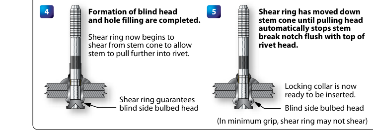
When only one side of a joint is accessible, solid-shank rivets cannot be bucked in the traditional way. Blind rivets solve this problem. The FAA recognizes several types, including the pull-type (pop rivet), the self-plugging friction-lock, and the self-plugging mechanical-lock. For structural applications, only mechanically locked blind rivets are approved — friction-lock types can lose their stem under vibration and are generally restricted to non-structural repairs. Always verify approval in the applicable Structural Repair Manual (SRM) or manufacturer documentation before using any blind fastener in a structural location.
Rivet Selection Standards
Diameter Selection
The rule of thumb for selecting rivet diameter is that the rivet shank diameter should be three times the thickness of the thickest sheet being joined. This relationship ensures the rivet can develop adequate shear strength across the joint. Rivet diameters are measured in 32nds of an inch: an AN470AD4 rivet has a shank diameter of 4/32 inch, or 1/8 inch. The digit(s) following the alloy code represent diameter in 32nds, while the final digits indicate shank length in 16ths of an inch.
Length and Grip Length
The exposed shank length that protrudes through the hole — the grip length — must be sufficient to form a proper shop head (the bucked head on the back side). The standard shop head should have a diameter equal to 1.5 times the rivet shank diameter and a height equal to 0.5 times the shank diameter. To achieve this, a general rule is that the rivet should protrude 1.5 times its own diameter beyond the material being joined before bucking begins. Selecting a rivet that is too short results in an undersized shop head; too long results in a bent or malformed shop head.
Hole Preparation
Holes must be drilled to the correct size for a snug but not forced fit. The rivet should slide into the hole under light finger pressure. Oversized holes allow the rivet to move before and during installation, reducing joint strength. For countersunk rivets, the countersink depth must match the rivet head angle (100°) and depth precisely: if the countersink is too deep, the rivet head sits below the skin surface (countersink too deep); if too shallow, the head stands proud. A knife-edge condition — where the countersink reaches entirely through the top sheet — is structurally unacceptable and must be repaired by dimpling or using a larger-diameter fastener with SRM approval.
Installation Standards and Inspection
A properly installed rivet joint is judged by both the manufactured head (the original factory head) and the shop head. The shop head must meet the 1.5D diameter and 0.5D height targets described above. Rivets that fail to meet these standards are categorized as defects:
- Overdriven (smashed) rivets: Shop head is too flat and too wide. The rivet material is over-worked, compromising strength.
- Underdriven rivets: Shop head is too tall and not wide enough — the rivet was not driven completely. Shear strength is inadequate.
- Driven off-center (clubbed head): The bucking bar was not held squarely, producing an asymmetric shop head that puts uneven stress on the hole.
- Cracked shop head: Indicates the rivet alloy has hardened (often a DD rivet used past its working window) or the material was improperly worked.
- Sheet-not-pulled-together (pillowing): A gap between sheets indicates the rivet was not long enough or the sheets were not held tightly during installation.
Rivet spacing and edge distance are also critical structural parameters. The minimum edge distance — the distance from the center of a rivet hole to the edge of the material — is typically 2 to 2.5 times the rivet diameter, depending on the application. Minimum rivet pitch (center-to-center spacing in a row) is typically 3 times the rivet diameter. Maximum pitch for structural joints is usually no more than 12 times the rivet diameter. These values should be verified against the applicable SRM, but the 2D minimum edge distance and 3D minimum pitch are the baseline values commonly tested on the AMT General exam.
Why It Matters
Every rivet in a primary structure is a load path. A single improperly installed or wrong-material rivet in a wing spar cap or fuselage longeron can initiate a fatigue crack under cyclic loading that, over time, propagates into a catastrophic structural failure. This is not an abstraction — aviation history contains accidents traced to improper fastener installation during maintenance. Additionally, using a rivet alloy that is incompatible with the base metal (for example, installing a 2024 rivet into a magnesium structure) accelerates galvanic corrosion that may be invisible beneath paint for years before becoming structurally significant.
Key Numbers and Rules
- 100° countersink angle for flush-head (AN426) rivets
- Shop head diameter = 1.5 × shank diameter (D)
- Shop head height = 0.5 × shank diameter (D)
- Protrusion before bucking ≈ 1.5 × D
- Rivet diameter selection rule: 3 × thickness of thickest sheet
- Minimum edge distance: 2–2.5 × D
- Minimum pitch: 3 × D; maximum pitch: 12 × D
- AD (2117-T4): no refrigeration needed; DD (2024-T4): freeze at ≤ 32°F, limited working time
- 5056 (B rivet): magnesium structures only
- Monel: stainless steel / titanium structures
Memory Aid
Use the phrase "All Driven Ducks Don't Bite" to remember the common rivet alloy-to-mark relationships in order of increasing strength: A (1100, no mark) → D (2017, one dot) → DD (2024, two dashes) → B (5056, cross). While not a traditional aviation mnemonic, it groups the four alloy families from softest/non-structural to structural, which helps you quickly answer identification questions on the exam.
Common Test Traps
- Confusing the countersink angle: Aircraft use 100° countersunk rivets. The FAA exam may list 82° or 90° as distractors — those are standard hardware angles, not aircraft rivet angles.
- DD rivet storage: Students forget that 2024-T4 rivets must be kept refrigerated and have a limited working time after removal. Exam questions may ask what to do when you have leftover DD rivets at end of the day — return them to cold storage, do not leave them at room temperature.
- Blind rivet structural approval: Not all blind rivets are approved for structural use. Only mechanically locked self-plugging types may be used in structural applications, and only with SRM authorization.
- Knife-edge condition: Countersinking through the full thickness of a thin sheet creates a knife edge — this is always a reject condition requiring additional action, not just a deeper countersink.
- 5056 rivet misapplication: Using a 2117 or 2024 rivet in a magnesium structure is a galvanic corrosion risk. Exams test whether you know the B (5056) rivet is specifically reserved for magnesium alloy structures.