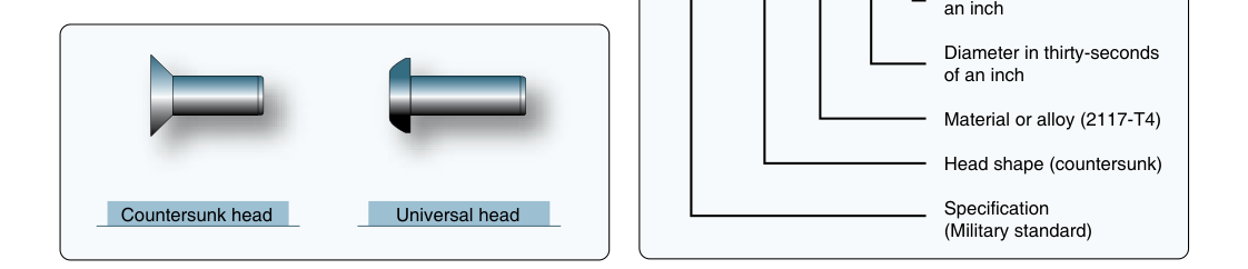
Solid shank rivets are the workhorses of aircraft sheet metal construction. Unlike blind rivets, which can be set from one side, solid shank rivets require access to both sides of the work: a driving force on the manufactured head side and a bucking bar held firmly against the shank on the opposite side. The result, when done correctly, is a tight, flush, and structurally sound fastener that meets the exacting dimensional tolerances demanded by aircraft maintenance standards. Understanding how and why each step of the process works — from hole preparation to final inspection — is essential knowledge for any Aviation Maintenance Technician (AMT) working on airframe sheet metal.
This article covers the full installation sequence, bucking bar selection and technique, the inspection criteria used to accept or reject a finished rivet, and the most commonly tested points on the FAA AMT Airframe knowledge exam.
Rivet Anatomy and Material Identification
A solid shank rivet consists of a manufactured head (the preformed head produced at the factory), a shank (the cylindrical body), and the grip length (the portion of the shank that fills the hole). When the rivet is driven, the protruding tail of the shank is upset into a shop head — also called the bucked head or driven head — by the force of the bucking bar.
Rivet alloy is identified by a two-digit number stamped on or color-coded on the head. The most common aircraft rivets are 2117-T4 (AD designation, dimple on head, no heat treatment required after manufacture — the most widely used general-purpose rivet), 2024-T4 (DD designation, two raised dashes, must be kept refrigerated after heat treatment and used within a limited time at room temperature), and 2017-T4 (D designation, one raised dash, also requires refrigeration). Aluminum alloy rivets in the 5000 series (such as 5056) are used with magnesium alloys to reduce galvanic corrosion. Steel and Monel rivets are used in high-temperature or high-strength applications.
Hole Preparation
A proper rivet installation begins with a correctly sized and finished hole. The hole diameter should be 0.003 to 0.004 inches larger than the nominal rivet diameter for most aluminum rivets — enough clearance for the rivet to slide in without forcing, but tight enough to fill cleanly when driven. Oversized holes result in loose rivets that cannot develop full shear strength.
Drilling sequence matters. Begin with a pilot drill smaller than the final size, then step up to the correct drill size. Drill bits are selected to match the rivet diameter: a No. 40 drill (0.098 inch) pairs with a 3/32-inch rivet, a No. 30 drill (0.128 inch) pairs with an 1/8-inch rivet, and a No. 21 drill (0.159 inch) pairs with a 5/32-inch rivet. Drill at a moderate speed with light, steady feed pressure to avoid work-hardening and burrs. After drilling, deburr both sides of the hole to ensure the rivet head seats flush and to prevent stress concentrations that could initiate fatigue cracks.
For countersunk (flush) rivet installations, the hole is dimpled or countersunk to accept a flat head rivet. Dimpling is used on thinner sheet and involves deforming the metal around the hole to create a conical recess; machine countersinking is used on thicker material and cuts away material to create the countersink. The countersink angle must match the rivet head angle — typically 100 degrees for AN426 countersunk rivets.
Rivet Selection: Length and Diameter
Selecting the correct rivet length is critical to forming an acceptable shop head. The general rule is that the shank should protrude beyond the material by 1.5 times the rivet diameter. This protruding tail, when upset, should form a shop head that is 1.5 times the rivet diameter in width and 0.5 times the rivet diameter in height. These dimensions define a structurally acceptable driven head.
To find required rivet length: measure the total grip (combined thickness of all sheets being joined), then add 1.5× the rivet diameter for the shop head. Round up to the next available standard rivet length, which come in 1/32-inch increments. For example, joining two sheets totaling 0.125 inch (1/8 inch) with a 1/8-inch rivet: 0.125 + (1.5 × 0.125) = 0.125 + 0.1875 = 0.3125 inch; round up to 3/8 inch grip length.
Bucking Bar Selection and Technique
The bucking bar is a hardened steel tool held against the rivet tail while the rivet gun drives from the manufactured head side. Selecting the right bucking bar is as important as choosing the rivet itself. Bucking bars come in a wide variety of shapes and weights to fit into tight structural areas. The flat face of the bar must be smooth and free of nicks — any surface defect will be transferred as a mark into the shop head.
Weight matters: a heavier bucking bar requires less physical force from the holder because its mass absorbs the gun's impact and transmits it efficiently into the rivet tail. Lighter bars require the holder to push harder to keep the bar from bouncing. As a general guideline, use a heavier bar in open areas and a specially shaped lighter bar only when access demands it.
The bucking bar technique requires the holder to press the bar firmly and squarely against the rivet tail at all times during the gun's operation. If the bar is held at an angle, the shop head will be off-center or canted — a reject condition. If the bar bounces away even momentarily, the rivet tail can mushroom unevenly or the sheets may be damaged. Communication between the gun operator and the bucker is critical in a two-person crew: a standard signal is for the bucker to tap the surface to signal readiness and for the gun operator to fire only after that confirmation.
Gun pressure (measured in PSI at the regulator) is adjusted so the rivet is driven with several short bursts rather than one sustained blast. This gives the operator control over how much material is being upset at once. Over-driving collapses the shop head too flat (a pancake head); under-driving leaves the tail insufficiently upset. Rivet guns are matched to rivet size: smaller, lighter guns for smaller rivets and thin sheet; heavier guns for larger or harder rivets.
Inspection of Driven Rivets
Every driven rivet must be inspected before the job is considered complete. The FAA and manufacturer standards specify the following accept/reject criteria:
- Shop head dimensions: width must be at least 1.5× rivet diameter; height must be at least 0.5× rivet diameter. A rivet head gauge (bucking bar gauge) can be used to verify these dimensions quickly.
- Manufactured head seating: the original head must sit flush and fully contact the sheet surface with no gap, tipping, or cracks in the surrounding metal.
- Shear cracks: any cracking in the shop head or surrounding skin is an immediate reject.
- Offset or canted shop head: if the center of the shop head is not aligned with the hole centerline, the rivet must be removed and replaced.
- Sheet damage: the skin must not be dented, gouged, or show tool marks from the gun or bucking bar. Slight bucking bar marks can be cause for rejection depending on the repair specification.
Rivet Removal
When a rivet must be removed, the goal is to remove the fastener without enlarging or elongating the hole. The standard technique is to drill out the manufactured head using a drill bit one size smaller than the rivet shank diameter — this avoids cutting into the sheet material. Drill only deep enough to separate the head from the shank, then use a pin punch to push the shank out from the head side. Never drill through the full shank, as this risks enlarging the hole. If a hole is elongated or oversized after removal, the next oversize rivet or a special repair procedure may be required.
Why It Matters
Riveted joints in aircraft are primary structural connections. A single improperly driven rivet in a row transfers its share of load to adjacent fasteners, increasing stress on them and accelerating fatigue cracking — a progression that can ultimately compromise the entire joint. The FAA Aviation Maintenance Technician Handbook – Airframe (FAA-H-8083-31) dedicates significant coverage to rivet installation because errors in this fundamental skill have real safety consequences. The same handbook forms the basis for the AMT Airframe knowledge test, so understanding these principles is both a safety imperative and an exam requirement.
Common Test Traps
- Shop head dimensions are frequently tested in reverse: remember it is 1.5× diameter in WIDTH and 0.5× diameter in HEIGHT — not the other way around.
- 2024-T4 (DD) rivets require refrigeration between heat treat and use; failing to refrigerate or exceeding the time limit at room temperature means they must be re-heat-treated before use. Many questions exploit this requirement.
- Drill size matching: a No. 30 drill is used for 1/8-inch rivets — if you confuse drill number (which gets smaller as diameter gets larger) with rivet size, you'll select the wrong drill on the test.
- Countersink vs. dimpling: machine countersinking in very thin material removes too much material, leaving a knife edge around the hole that is too thin to carry load; dimpling is the correct approach for thin sheet.
- Rivet length calculation: the exam often presents total grip thickness and asks for minimum rivet length; always add 1.5× the diameter to the grip length, then round UP to the next standard length — never round down.