When aircraft designers specify a smooth exterior surface — whether to reduce aerodynamic drag on a high-speed fuselage skin or to meet structural assembly standards — flush rivets are the answer. Unlike universal-head (AN470) rivets, which protrude above the surface, flush or countersunk (AN426) rivets sit perfectly even with the surrounding skin. Achieving that flush fit, however, requires careful preparation of the hole itself. Two methods accomplish this: countersinking, which machines a tapered recess directly into the material, and dimpling, which cold-forms a matching cone shape into the sheet. Understanding when to use each method, and how to execute both correctly, is essential knowledge for any airframe technician — and a consistently tested topic on the AMT Airframe knowledge exam.
Both techniques ultimately create a conical seat whose angle matches the rivet head. The most common flush rivet head angle used in aircraft construction is 100 degrees, which corresponds to the AN426 rivet series. The sheet metal preparation must produce a seat with precisely that included angle so the rivet head contacts the material fully around its perimeter, distributing load evenly and preventing stress concentrations or premature failure.
Countersinking: Machining the Seat
Countersinking removes material from the hole entrance to create the tapered recess. A countersink cutter — essentially a piloted rotating cutting tool — is chucked into a drill motor or a dedicated microstop countersink cage. The pilot portion fits into the drilled hole to keep the cutter centered, while the cutting flutes machine away the surrounding material at the correct included angle, most commonly 100 degrees for aircraft work.
The depth of a countersink is the critical variable. The goal is for the rivet head to sit flush with — or just barely below — the top surface of the material when fully driven. Technicians verify depth with a rivet head flush gauge or by test-fitting a sample rivet: the head should rest flush without rocking, and a straightedge laid across the surface should not show a gap or a proud head. Slightly under-countersinking is preferable to over-countersinking; a rivet that stands a fraction high can be corrected by deepening the countersink slightly and re-testing per the SRM, but one that drops below the surface into an over-cut hole has compromised the surrounding material. Filing the rivet head down to force it flush is not an acceptable practice — filing can damage the head and reduce its shear strength.
Microstop Countersink Cage
Production shops almost universally use a microstop countersink cage rather than a freehand cutter. The cage clamps onto the drill motor nose and holds the cutter at a precisely adjusted, repeatable depth. A micrometer-style collar allows depth adjustment in increments as fine as 0.001 inch. The technician sets depth on scrap material of the same thickness and rivet size, verifies the fit with a sample rivet, then runs every production hole to that identical depth. This eliminates the variability of hand-feel and greatly reduces over-countersinking errors. On exam questions, recognize that the microstop cage is the preferred production tool for consistent countersink depth control.
When Countersinking Is Appropriate
Countersinking is only appropriate when the base material is thick enough that removing the conical volume of material still leaves adequate structural thickness underneath. As a practical rule derived from FAA guidance, the remaining material below the countersink (sometimes called the land) must not be reduced to a knife edge. If the material is so thin that the countersink would extend entirely through it — creating what is called a knife-edge condition — the joint loses clamping area and the rivet can pull through under load. In such cases, dimpling is the correct choice. A common shop benchmark is that countersinking is generally suitable when the material is at least as thick as the depth of the countersink itself, approximately equal to the rivet head height.
Dimpling: Cold-Forming the Seat
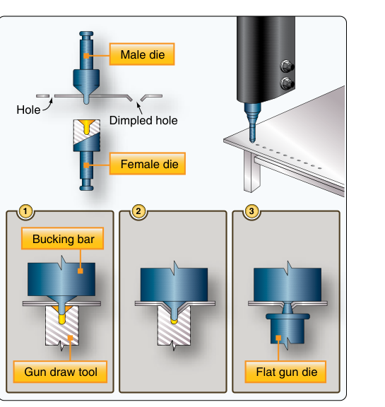
Dimpling displaces rather than removes material. A matching male-and-female dimple die set — also called a punch and die — is pressed together with the sheet metal sandwiched between them. The male die has a conical projection matching the rivet head angle (100 degrees for AN426 rivets), and the female die has the corresponding recess. When force is applied — by a hand squeezer, pneumatic squeezer, or a dedicated dimpling machine — the sheet metal deforms permanently around the male die, creating a raised conical nest on one face and a corresponding depression on the other.
After dimpling, the dimple itself protrudes slightly on the back (inner) side of the skin. When two dimpled sheets are to be joined, the outer skin is dimpled and the inner structural member (such as a spar flange or rib) must either be coin dimpled (dimpled with a special flat-bottomed die that flattens the back side) or countersunk to accept the protruding dimple of the outer skin — a practice called dimple-to-countersink. This nested arrangement maintains a flat mating surface between sheets and preserves full bearing area.
Types of Dimpling
- Hand dimpling — A simple C-frame squeezer with dimple dies. Used for accessibility in repair work or small quantities. Consistent results require careful alignment.
- Pneumatic squeezer dimpling — Faster and more consistent than hand dimpling; the most common shop method for individual repairs.
- Machine dimpling (radius die method) — A dedicated press with precisely matched dies. Produces the highest quality dimple and is standard in production manufacturing of aluminum skins.
- Hot dimpling — Applied to harder alloys (such as 2024-T3 in heavier gauges) or to thermoplastic composite skins where cold-forming would crack the material. A heated die softens the material locally before forming. Less common in general aviation repair but important in transport-category structures.
Dimpling vs. Countersinking: Choosing the Right Method
The fundamental decision rule is based on sheet thickness relative to rivet diameter. FAA guidance and AC 43.13-1B (the Acceptable Methods document widely referenced alongside the handbooks) establish that for very thin sheet — typically sheet thinner than approximately the rivet head height — dimpling is required because countersinking would produce a knife edge. For thicker material where sufficient land remains, countersinking is acceptable and is often preferred because it produces a flatter back face that simplifies assembly. In practice, most aluminum skins in the range of 0.020 to 0.040 inch thickness are dimpled, while skins thicker than about 0.040 inch (depending on rivet size) may be countersunk.
The alloy also matters. 2024-T3 aluminum, the most common aircraft structural alloy, is relatively ductile and dimples well in normal gauges. 7075-T6, being harder and more brittle, is more prone to cracking during cold dimpling and may require hot dimpling or, in thicker sections, countersinking. Technicians must consult the aircraft's structural repair manual (SRM) and applicable FAA guidance for the specific material and application.
Key Numbers and Rules
- 100-degree included angle — Standard head angle for AN426 (100° flush) rivets; countersink and dimple dies must match this angle.
- Knife-edge rule — Never countersink so deeply that the remaining material wall is reduced to a sharp edge; switch to dimpling when material is too thin.
- Microstop cage — Preferred countersink depth control tool; allows adjustment to ±0.001 inch increments.
- Dimple die matching — Male and female dies must match in both angle and rivet shank diameter; mismatched dies produce distorted dimples that prevent flush seating.
- Flush tolerance — Driven rivet heads on exterior skins must typically be flush to within +0.004 / -0.000 inch (check applicable SRM); heads that stand proud above this tolerance cause drag and must be corrected.
- Back-side clearance — When dimpling, the protruding back of the dimple must be accounted for; mating structure must be counter-dimpled or countersunk to nest the dimple properly.
Common Test Traps
- Confusing when to countersink vs. dimple. The exam often presents a scenario with a thin skin and asks which method is appropriate. Remember: thin skin = dimple; thick enough material = countersink. Countersinking thin material produces a knife edge and is incorrect.
- Forgetting the 100-degree angle requirement. Some questions offer 82-degree or 120-degree options. AN426 rivets are 100 degrees; dies and cutters must match exactly or the rivet will rock in the seat or stand proud.
- Assuming dimpling always leaves a perfectly flat back surface. Standard dimpling raises the material on the back face. If the back surface must be flat (e.g., to mate with a structural member), coin dimpling or a countersunk mating part is required.
- Microstop cage depth adjustment direction. Exam items sometimes ask about setting countersink depth. Know that the microstop cage is always set and verified on scrap material of identical thickness before production holes are cut — never set depth by feel on the actual part.
- Overdriving after improper countersinking. A countersink that is too deep cannot be corrected by driving the rivet harder. The rivet head will drop below flush, the material perimeter is already gone, and the only correct repair is to move to the next larger rivet size or stop-drill and re-prepare the hole per the SRM.