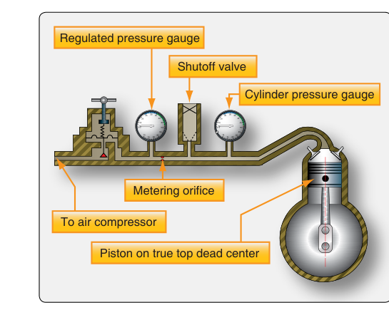
One of the most valuable diagnostic tools in an aviation maintenance technician's arsenal is the differential compression test. Unlike a simple compression test that measures peak cylinder pressure during cranking, the differential compression test applies a regulated, known pressure to a cylinder and measures how much of that pressure leaks past the rings, valves, or cylinder walls. This controlled comparison between applied pressure and retained pressure gives the technician a precise, repeatable picture of a cylinder's internal condition — without disassembling the engine.
Because piston rings, intake and exhaust valves, and cylinder walls are the primary sealing surfaces inside a reciprocating engine, their condition directly determines how efficiently combustion pressure is converted into crankshaft torque. A cylinder that leaks excessively will produce less power, consume more oil, and may eventually fail in service. The differential compression test is the FAA-accepted method for detecting such deterioration during 100-hour and annual inspections, as well as any time abnormal engine performance warrants investigation.
How the Differential Compression Test Works
The test uses a specialized tester that incorporates two pressure gauges and a calibrated restrictor (orifice) between them. Regulated shop air — commonly set at 80 PSI, though the exact calibration pressure can vary by tester and manufacturer procedure — is introduced on the upstream side of the orifice. The downstream side of the tester is connected to the cylinder through the spark plug hole. The orifice is sized so that a perfectly sealed cylinder will show equal pressure on both gauges (80 PSI in, 80 PSI in the cylinder). Any leakage past the rings, valves, or cylinder walls allows downstream pressure to drop, and the difference between the two gauge readings is the measure of cylinder leakage.
The result is expressed as a ratio: retained pressure over applied pressure, for example 72/80. A higher retained value indicates less leakage and better cylinder health. FAA-H-8083-32 offers 60/80 PSI (25% leakage) as a general guideline for airworthy cylinders, but engine manufacturers specify their own acceptable leakage limits, which can vary. Always defer to the specific engine manufacturer's maintenance manual for exact limits before condemning a cylinder or scheduling removal.
Step-by-Step Test Procedure
Performing a differential compression test correctly requires careful preparation and attention to safety. The engine must be at operating temperature — a cold engine has tighter fits between its components, and oil has not yet redistributed evenly, which can give misleadingly optimistic readings. Run the engine until normal operating temperature is achieved, then shut it down and allow it to cool only enough for safe handling.
- Remove all spark plugs from all cylinders. Removing every spark plug, not just those on the cylinder being tested, allows the engine to be rotated by hand with much less resistance. Each cylinder is then tested individually through its own spark plug hole.
- Position the piston at top dead center (TDC) on the compression stroke. This is critical. If the piston is not at TDC on the compression stroke, shop air introduced into the cylinder will drive the crankshaft to rotate suddenly and with significant force. A propeller that snaps unexpectedly can cause serious injury. To find TDC on the compression stroke: rotate the propeller by hand in the direction of normal rotation while covering the spark plug hole with your thumb. When you feel air pressure building against your thumb and the thumb hole is blocked, both valves are closed — continue rotating slowly until the piston reaches the top of its travel. Use a TDC indicator or a wooden dowel through the spark plug hole to confirm the piston is at the very top.
- Connect the compression tester to the cylinder through the accessible spark plug hole using the appropriate adapter fitting. Ensure the tester's shutoff valve is closed before connecting.
- Apply regulated shop air at the tester's specified pressure (commonly 80 PSI) to the tester inlet. Open the tester valve slowly — a rapid application of pressure can also rotate the crankshaft if the piston is not perfectly positioned.
- Read both gauges simultaneously. Record the upstream (applied) pressure and the downstream (cylinder) pressure. The difference is the leakage value.
- Listen carefully while pressure is applied. The location of air escaping tells you which sealing surface has failed.
Diagnosing Leak Location by Sound and Feel
The differential compression test is not just a pass/fail measurement — it is a diagnostic procedure. Where the air escapes is as important as how much escapes. By listening and feeling at specific locations while the cylinder is pressurized, the technician can pinpoint the source of leakage:
- Air escaping from the carburetor or air intake: indicates a leaking or burned intake valve. The air is flowing back through the open intake pathway.
- Air escaping from the exhaust pipe or exhaust stack: indicates a leaking or burned exhaust valve. The air exits through the exhaust system.
- Air escaping from the crankcase breather or oil filler cap: indicates worn or broken piston rings, or possible cylinder wall scoring. Pressure is bypassing the rings and entering the crankcase.
- Air escaping from an adjacent cylinder's exhaust or intake: may indicate a cracked cylinder head or a blown head gasket between cylinders, though this is less common on air-cooled engines without head gaskets in the traditional sense.
- Bubbles in the coolant overflow tank (on liquid-cooled engines): would indicate a cracked block or head gasket leak into the cooling system.
A trained technician does not simply document numbers — they walk around the engine and listen. A leaking exhaust valve that does not yet push leakage past the 25% threshold can still be trended over successive inspections, and a pattern of steady decline is itself a warning sign.
Why the Differential Compression Test Matters
The FAA requires that certificated aircraft with reciprocating engines undergo regular inspection. During a 100-hour or annual inspection, compression testing is a standard element of the engine inspection process. The differential method is preferred over a simple cranking compression test because it is independent of starter motor speed, battery condition, and cranking technique — all factors that can influence the results of a cranking test and make comparisons unreliable from one inspection to the next.
The differential test also provides actionable diagnostic information that a simple compression gauge cannot. Knowing that leakage is past the exhaust valve, for instance, allows the technician to schedule a valve job or cylinder replacement before an in-flight power loss occurs. This is exactly the kind of condition-monitoring philosophy that underpins FAA maintenance standards: catch deterioration early, trend it over time, and take corrective action before safety is compromised.
Key Numbers and Rules
- Applied (regulated) pressure: commonly 80 PSI, though the specific calibration pressure depends on the tester and manufacturer procedure in use.
- General guideline for acceptable leakage: FAA-H-8083-32 cites 60/80 PSI (25% leakage) as a general benchmark for an airworthy cylinder — but always use the engine manufacturer's specific limits, which can vary.
- Piston position: must be at TDC on the compression stroke (both valves closed) — not TDC on the exhaust stroke.
- Engine temperature: test must be performed with the engine at or near normal operating temperature for valid results.
- Trending: a single reading is less valuable than a series of readings over multiple inspections; a downward trend demands investigation even if individual readings are within limits.
- Documentation: results should be recorded in the aircraft maintenance records with the date, engine total time, and individual cylinder readings (e.g., 74/80, 76/80) for future reference.
Common Test Traps
- Testing a cold engine. Cold metal has different clearances than a warm engine, and residual oil on cylinder walls can temporarily seal rings. A cold test will often show better-than-actual results. Always test at operating temperature.
- Piston not at TDC on the compression stroke. This is a safety hazard and also an invalid test. Air pressure will push the piston down and rotate the crankshaft if even one valve is open. Confirm both valves are closed before applying air.
- Misidentifying which stroke the piston is on. The engine has two TDC positions per cylinder per cycle — one on the compression stroke and one on the exhaust stroke. Only the compression stroke TDC (both valves closed) is correct for this test. Verify by feeling for pressure buildup at the spark plug hole as you rotate toward TDC.
- Ignoring the location of the leak. A borderline reading with air hissing from the exhaust stack is far more significant than a borderline reading with slight crankcase breathing, because a burned exhaust valve can deteriorate rapidly and cause a sudden power loss. Leak location context is essential.
- Using a single test result to condemn or approve a cylinder without trending data. An engine that has been sitting for months, or one recently returned from overhaul, will have different ring seating characteristics. Multiple data points over time give the most reliable picture of cylinder health.