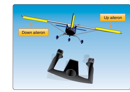
Ailerons are the primary roll-control surfaces on a fixed-wing aircraft, and their correct rigging is one of the most safety-critical tasks an aviation maintenance technician (AMT) can perform. Improper aileron rigging can produce sluggish roll response, unintended roll tendencies, excessive adverse yaw, or even control reversal in extreme cases. Every adjustment made during aileron rigging must be verified against the aircraft manufacturer's maintenance manual — the manual is always the governing authority — and backed by a thorough understanding of the principles involved. This article walks through those principles, the step-by-step rigging process, the concept of differential travel, and the practical traps that catch technicians and exam candidates alike.
How Ailerons Produce Roll
Ailerons work in opposition: when the pilot moves the control wheel or stick to the right, the right aileron deflects upward and the left aileron deflects downward simultaneously. The downward-deflecting aileron increases the camber and lift on the left wing, while the upward-deflecting aileron decreases lift on the right wing. The resulting lift differential produces a rolling moment toward the right. The mechanical linkage connecting the cockpit control to both ailerons is typically a combination of cables, pulleys, bellcranks, pushrods, and turnbuckles. Each element in this system must be properly aligned, tensioned, and adjusted before the aircraft is returned to service.
The Concept of Differential Aileron Travel
A naive rigging scheme would deflect both ailerons by equal and opposite amounts. However, aerodynamic drag is not symmetric with deflection direction. A downward-deflecting aileron produces significantly more induced drag than an upward-deflecting aileron at the same angular displacement. This asymmetry creates adverse yaw — a tendency for the nose to yaw toward the wing with the rising aileron (the opposite of the intended turn direction) whenever the pilot initiates a roll. If not corrected, the pilot must apply substantial rudder on every roll entry, and coordinated flight becomes difficult.
Aircraft designers address adverse yaw through differential aileron travel, sometimes called differential linkage or differential rigging. In a differentially rigged system, the upward-deflecting aileron travels through a greater angular range than the downward-deflecting aileron. For example, an aileron might be rigged to travel 20 degrees upward but only 15 degrees downward. The larger upward deflection reduces lift more on the descending wing without generating the large drag spike that a large downward deflection would create on the opposite wing. The result is more balanced drag on both wings during a roll, greatly reducing adverse yaw.
Differential travel is built into the geometry of the bellcrank or control horn — not usually through separate adjustment points. The mechanic's job is to confirm that the manufactured-in differential is preserved during reassembly and that wear or damage has not altered the effective geometry. The rigging process verifies these travel limits with a protractor or inclinometer against the values published in the maintenance manual.
Aileron Rigging Procedures
Pre-Rigging Inspection
Before any adjustment is made, perform a complete inspection of the entire aileron system. Check for correct installation of all hardware, absence of corrosion on pulleys and cables, freedom of movement at every hinge point, proper safety wiring or cotter pins at rod-end bearings, and correct cable routing through all pulleys and fairleads. Pulleys must rotate freely and cable must ride in the groove without rubbing on the guard or sidewalls. Any defects must be corrected before rigging begins.
Neutralizing the System
Rigging always begins at a known reference point. Place the cockpit control (wheel or stick) in the neutral position, typically confirmed by using a rigging fixture or by aligning a reference mark on the control column. Simultaneously, the ailerons must be held at their neutral (faired) position, flush with the wing trailing edge or at the manufacturer-specified neutral datum. Many manufacturers specify the use of a rigging pin or alignment jig to hold the control surface precisely at neutral while initial adjustments are made.
Setting Cable Tension
With the system neutralized, cable tension is adjusted using the turnbuckles. A tensiometer is the proper tool for measuring cable tension; it measures the load in pounds and must be matched to the correct cable diameter. Published tension values vary by aircraft type, cable diameter, and even ambient temperature, because cable tension changes as the airframe expands and contracts thermally. The maintenance manual will provide a tension-versus-temperature chart or table; the technician must record the shop temperature and use the corresponding tension value. Over-tensioning a cable can bow the airframe structure and create excessive friction; under-tensioning allows slack that can cause control slop or cable jump on pulleys during abrupt inputs.
After setting tension on one cable run, recheck the opposing cable, because adjusting one turnbuckle affects tension throughout the interconnected system. Iterate adjustments until both cables read within limits simultaneously while the surfaces remain neutral.
Checking and Setting Travel Limits
Once cable tension is correct, measure aileron deflection using a rigging protractor or digital inclinometer placed on the aileron surface. Deflect the aileron to its full up and full down positions by moving the cockpit control to its stop, and record the deflection angles. Compare each reading — separately for up travel and down travel on each aileron — with the maintenance manual limits. If travel is insufficient, adjust the stops (typically mechanical stop bolts on the bellcrank or in the cockpit) to allow more movement. If travel is excessive, the stops must be repositioned to limit travel. Never allow a control surface to contact any structural member at full deflection; the stop must positively limit travel before structural contact occurs.
Because of differential rigging, the up travel and down travel numbers will intentionally differ. For example, if the manual calls for 20 degrees up and 15 degrees down (plus or minus 1 degree tolerance), confirming that both values are within tolerance on both ailerons demonstrates the differential geometry is intact. Document all measured values on a rigging record.
Checking Symmetry and Centering
After travel limits are confirmed, verify that the aileron system is symmetric: with the cockpit control centered, both ailerons should sit at their neutral position simultaneously. Move the control smoothly through its full range in both directions and check that the system moves freely without binding, that stops are contacted evenly, and that there is no slop or lost motion at neutral. A free-play check — rocking the surface gently by hand with the control held fixed — should produce only the minimal movement allowed by the manufacturer (often measured in fractions of an inch at the trailing edge).
Turnbuckle Safety
After all adjustments are complete and verified, every turnbuckle must be safetied. The FAA accepts two primary methods: safety wire (the traditional method, using stainless safety wire threaded through the barrel and around the shanks) and clip-type safetying devices approved for the specific turnbuckle. The critical inspection criterion is the thread-engagement check: no more than three threads of either terminal shank may be exposed beyond the barrel ends. This ensures sufficient thread engagement to carry the design load.
Why It Matters
Incorrect aileron rigging can produce a permanently banked aircraft, requiring constant opposite aileron pressure to maintain wings-level flight. Insufficient travel limits emergency roll authority during crosswind landings or upset recovery. Excessive travel can overload the airframe in aggressive maneuvers. An improperly safetied turnbuckle can unravel in service, resulting in cable failure and total loss of roll control. These outcomes underscore why rigging is treated as a return-to-airworthiness task requiring an AMT signature and, for most aircraft, an inspection authorization (IA) signoff on the maintenance record.
Key Numbers and Rules
- Differential travel: Upward aileron deflection is greater than downward deflection; exact values are aircraft-specific and always found in the maintenance manual.
- Thread exposure rule: No more than three threads of a turnbuckle terminal may be exposed beyond the barrel after tightening.
- Cable tension tool: A tensiometer calibrated to the specific cable diameter is required; substitute measurements are not acceptable.
- Temperature correction: Cable tension specifications must be applied at the measured ambient temperature using the manufacturer's temperature-tension chart.
- Control stop placement: Mechanical stops must contact before any structural member is reached at full deflection.
- Free-play limits: Maximum allowable free play (slop) at the trailing edge is specified per aircraft type; typical values are a fraction of an inch.
- Documentation: All rigging measurements must be recorded in the aircraft maintenance record per 14 CFR Part 43.
Common Test Traps
- Confusing which aileron travels farther: The upward-deflecting aileron (on the descending wing side) has the greater travel in a differential system, not the downward-deflecting one. Many candidates reverse this.
- Forgetting temperature correction: Cable tension limits are only valid at a specific temperature. Using a tension value from the table at 70°F when the shop is 40°F will produce an over-tensioned system once the aircraft warms up.
- Three-thread rule confusion: The rule says no MORE than three threads exposed — meaning if you can count four threads outside the barrel, the turnbuckle is under-engaged and unsafe, even if the system passes tension checks.
- Assuming rigging equals adjustment: Rigging also includes inspection, confirmation of correct hardware, safetying, and documentation. Skipping any of these steps makes the task incomplete regardless of how well the travel was set.
- Ignoring the opposite side: Adjusting a turnbuckle on one side changes tension on the opposite cable run. Both cables must be re-measured after every adjustment; checking only one side is a common shortcut that produces out-of-tolerance results.