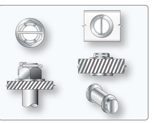
Among the most fundamental skills an aviation maintenance technician (AMT) must master is the ability to install and inspect safety devices on threaded fasteners. Safety wire and cotter pins serve one essential purpose: they prevent vibration and rotational forces from backing fasteners out of their secured positions. A loose bolt on an airframe, engine, or flight control linkage is not a minor inconvenience — it is a potential catastrophe. The FAA expects AMT candidates to understand not just how to perform these installations, but how to critically evaluate them during routine inspections. A properly trained technician can identify an incorrect or compromised safety device at a glance.
This article covers the principles, procedures, and inspection criteria for both safety wiring and cotter pin installations as grounded in FAA guidance, particularly the Aviation Maintenance Technician Handbook — General (FAA-H-8083-30).
Why Locking Devices Are Required
Threaded fasteners rely on friction and preload (clamping force) to remain in place. Under the cyclic vibration common in aircraft engines and airframes, that friction can diminish over time. When a fastener backs out even slightly, the clamping force drops, causing even faster loosening — a classic self-reinforcing failure mode. Secondary locking devices, including safety wire and cotter pins, create a positive mechanical barrier against this rotation. Unlike thread-locking compounds (which have their own applications), safety wire and cotter pins are inspectable — a technician can visually verify their integrity without disassembly.
Safety Wiring: Principles and Correct Installation
Safety wire works by connecting two or more fasteners (or a fastener to an adjacent structure) in such a way that any tendency of a fastener to rotate in the loosening direction is resisted by tension in the wire. The wire must always be routed so that it pulls the fastener in the tightening direction. Routing the wire in the wrong direction is a common error — and a critical one, because a wire under the wrong tension actually encourages loosening.
Wire Gauge Selection
Safety wire is available in several standard diameters — commonly 0.020, 0.025, 0.032, and 0.041 inch — with stainless steel as the aviation standard material. The correct diameter for a given application is specified by the applicable maintenance manual or standard practices guidance (AC 43.13-1B, Chapter 7, Table 7-1); 0.032-inch stainless steel wire is widely used on general aircraft fasteners, but smaller wire such as 0.020-inch is common on lighter applications such as small screws or fittings. Copper or brass wire is occasionally used in non-ferrous applications, but stainless steel remains the standard. The wire diameter must be appropriate to the fastener size — using undersized wire risks breakage under tension, while oversized wire can be difficult to route through small holes and may not achieve the proper twist density.
Twisting and Tension
Once routed through the safety wire holes, the wire must be twisted uniformly to create a neat, pigtail-like braid. AC 43.13-1B calls for approximately 8 to 10 twists per inch (not counting the loop). Fewer twists result in a loose, floppy installation that provides inadequate resistance; more twists can work-harden the wire and make it brittle, causing early fatigue failure. The finished wire must be taut — snug against the fastener heads — but must not be so tight that it is under excessive tension at rest, as this will cause it to break during normal vibration.
Pigtail and Termination
After the final twist, the wire is bent back (the pigtail) and tucked or folded so it does not create a snag hazard. The standard pigtail length is approximately three to six twists (about 1/4 to 1/2 inch) after the last fastener connection, then cut and folded back against the wire bundle. Sharp, protruding wire ends are a safety hazard to both the aircraft structure and maintenance personnel — any installation with a sharp, unfolded pigtail should be rejected during inspection.
Single-Wire vs. Double-Wire Methods
Two basic techniques exist. The double-twist method (most common) uses a length of wire threaded through the hole in one fastener, both ends brought together and twisted, then threaded through the next fastener and twisted again. The single-wire method is used only on small screws in close proximity (such as oil filler caps or small inspection plate screws) where the double-wire method is impractical. Single-wire installations are generally limited to the situations specifically approved by the applicable manufacturer's maintenance manual.
Cotter Pin Installations: Principles and Correct Installation
Cotter pins (also called cotter keys) are used to lock castellated or slotted nuts on bolts and clevis pins. They are typically made from soft steel, stainless steel, or occasionally other corrosion-resistant alloys. The cotter pin passes through a hole drilled in the bolt shank and engages a slot in the castellated nut, positively preventing rotation.
Proper Installation Procedure
The castellated nut is first torqued to the low end of the specified torque range. If the slots do not align with the cotter pin hole, the nut is tightened (never loosened) until alignment is achieved, provided the torque remains within the specified range. If alignment cannot be achieved within the acceptable torque range, the bolt and nut combination must be changed — never undertighten a fastener simply to align the cotter pin hole. Once aligned, the cotter pin is inserted so the head (the loop end) seats against the face of the nut. One prong is bent over the end of the bolt (wrapping around the end or bending flat across the top), and the other prong is bent down against the flat of the nut. Both prongs must be bent — a cotter pin with only one prong bent is not an acceptable installation.
Cotter Pin Sizing
Per AC 43.13-1B, the cotter pin should be the largest diameter that will fit the cotter pin hole in the bolt, fitting snugly with minimal clearance. Using a pin that is too small leaves excessive play and provides inadequate locking. Cotter pins are also a one-time-use item — they must never be reused. The act of bending the prongs work-hardens the metal at the bend, and straightening and rebending will cause the pin to crack or break.
Inspection Criteria: What to Look For
During an inspection, the technician must evaluate safety wiring and cotter pin installations systematically. The following criteria apply:
- Correct direction of pull: Safety wire must pull fasteners in the tightening direction. Trace the wire route and confirm that loosening rotation would tension the wire, not relax it.
- Twist uniformity and density: Look for 8–10 twists per inch across the entire length of the wire. Sections with sparse or no twisting are cause for rejection.
- Wire condition: Inspect for kinks, corrosion, fraying, or any sign of breakage. A kinked or nicked wire has dramatically reduced strength and must be replaced.
- Pigtail condition: The pigtail must be folded back safely, not protruding sharply. A wire end pointing outward into the airstream or toward a moving part is a hazard.
- Proper gauge: Verify the wire gauge is appropriate for the application as called out in the maintenance manual or standard practices manual.
- Cotter pin prong condition: Both prongs must be fully bent. Check that prongs have not cracked at the bend, which is a sign the pin may have been reused.
- Cotter pin size: The pin must be the largest size that fits the hole snugly with minimal clearance. A visibly thin pin rattling in an oversized hole is unacceptable.
- No reused cotter pins: Cotter pins removed during maintenance must always be replaced with new ones.
- Proper nut engagement: For castellated nuts, verify that the nut is fully engaged on the threads (at least flush with the bolt end) and that the cotter pin slot alignment was achieved within the proper torque range.
Common Test Traps
- Wire direction trap: The FAA knowledge test frequently asks about the correct direction of wire pull. Remember — the wire must resist loosening, meaning tension in the wire is created when the fastener attempts to turn in the loosening direction. Many students incorrectly assume any installed wire is correct.
- Twist count confusion: Candidates sometimes confuse the twist specification (8–10 twists per inch) with pigtail length (3–6 twists before cutting). These are two separate requirements.
- Undertightening for alignment: A classic trap: the correct action when a castellated nut slot does not align is to tighten within the allowable torque range, never to loosen. Loosening to achieve alignment is always wrong.
- Cotter pin reuse: Questions may present a scenario where a cotter pin is removed and reinstalled. This is always incorrect — cotter pins are single-use items regardless of appearance.
- Single vs. double-wire method: Some questions describe a scenario where a single wire is used on large fasteners. Unless specifically authorized by the maintenance manual, the double-twist method is the standard for most aircraft fasteners.
Practical Inspection Mindset
Good technicians develop a pattern for inspecting these devices. During an inspection, work methodically around the component — engine accessory case, flight control bellcrank, landing gear assembly — and verify every safetied fastener before moving on. Do not assume that because adjacent fasteners look correct, all of them are. Vibration, heat cycling, and maintenance errors can affect individual fasteners while leaving neighboring ones intact. Document any discrepancy found and correct it before returning the aircraft to service. The goal is not merely to pass inspection but to ensure that no fastener can work itself loose in flight.
Mastering the inspection of safety wiring and cotter pins is one of the clearest demonstrations of an AMT's attention to detail and commitment to airworthiness. The FAA knowledge test will probe this area precisely because the consequences of getting it wrong are severe — and the correct techniques are well-defined and learnable.