When a crack or other discontinuity lurks inside a steel landing-gear strut or a ferromagnetic engine crankshaft, it may be invisible to the naked eye yet still pose a catastrophic structural hazard. Magnetic particle inspection (MPI) gives aviation maintenance technicians a reliable, non-destructive method to find those hidden flaws without cutting, grinding, or otherwise harming the part. Understanding why MPI works — not just how to perform the steps — makes technicians far more effective in selecting the right technique and interpreting results correctly.
MPI is classified as a non-destructive inspection (NDI) or non-destructive testing (NDT) method. It is covered in the FAA Aviation Maintenance Technician Handbook — General (FAA-H-8083-30), which provides the foundational theory and procedural guidance that every AMT is expected to know for both the knowledge test and practical work on certificated aircraft.
The Physics Behind Magnetic Particle Inspection
To understand MPI you first need to understand magnetic flux. When any ferromagnetic material — iron, nickel, cobalt, and their alloys — is magnetized, invisible lines of magnetic force called flux lines flow through the material in a predictable path. In a smooth, homogeneous piece of metal, virtually all of those flux lines stay inside the material. A crack, inclusion, void, or other discontinuity interrupts that smooth path and forces some flux lines to exit the surface and re-enter on the other side of the defect. This escaping field is called a flux leakage field.
Flux leakage fields are the key to MPI. When fine ferromagnetic particles — in dry powder or suspended in a liquid carrier — are applied to the magnetized part, they are attracted to and accumulate at any location where flux is leaking out. The resulting particle indication outlines the shape and orientation of the underlying discontinuity, making it visible to the technician. Because the flux must actually leak out of the surface, MPI is most sensitive to surface and near-surface flaws. Deeply buried internal defects do not create enough surface leakage to produce a reliable indication, which is why MPI is paired with ultrasonic or radiographic methods when deep subsurface flaws are a concern.
Ferromagnetic Limitation
MPI works only on ferromagnetic metals. Many modern aircraft use aluminum, titanium, magnesium, and composite structures — none of which can be magnetized and none of which are candidates for MPI. On those materials, technicians turn to dye-penetrant inspection, eddy-current inspection, or ultrasonic testing instead. Always confirm the alloy before selecting an inspection method; applying MPI procedures to a non-ferromagnetic part wastes time and provides no useful data.
Magnetization Methods
The way a part is magnetized determines which discontinuity orientations will be detected. This is one of the most important — and most tested — concepts in MPI theory.
- Circular magnetization: Electrical current is passed directly through the part (or through a central conductor threaded through hollow parts). The resulting magnetic field encircles the part's long axis. This orientation is best at detecting longitudinal discontinuities — cracks that run parallel to the long axis of the part, because they cross the circular flux lines at roughly 90 degrees.
- Longitudinal magnetization: The part is placed inside a coil (solenoid) or magnetized end-to-end using a yoke or bar magnet. Flux lines run along the length of the part. This configuration is best at detecting transverse discontinuities — cracks that run perpendicular to the long axis.
The general rule: a discontinuity is most visible when the magnetic flux crosses it at or near 90 degrees. Indications become weak and may disappear when flux runs parallel to the crack. Practically, this means technicians must magnetize the part in at least two perpendicular directions to ensure complete coverage of all possible crack orientations.
Magnetization Equipment
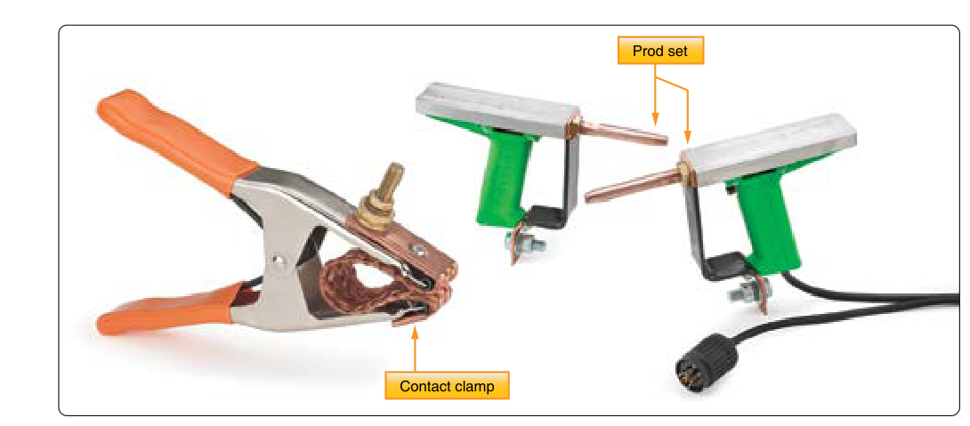
Common equipment includes the wet horizontal bench unit (a stationary machine that magnetizes parts and applies liquid particle bath simultaneously), portable yokes (U-shaped electromagnets or permanent magnets ideal for field use on large structures), prods (hand-held electrodes that pass current through a localized area), and coils for longitudinal magnetization. Portable yokes are particularly common for in-situ inspections on airframe components because they require no direct electrical contact with the part and minimize the risk of arc burns.
Types of Magnetic Particles and Application Methods
Particles come in two main forms:
- Dry particles: Fine iron powder, often colored (red, gray, yellow) for contrast against the part surface. They are applied as a cloud or dusted onto the part and work well for field inspections, rough surfaces, and elevated-temperature surfaces where a wet bath would evaporate.
- Wet particles: Iron oxide or iron particles suspended in a light oil or water carrier. The suspension — called the magnetic bath — is flowed or sprayed over the part. Wet method particles are smaller and provide better sensitivity for fine, tight cracks. Fluorescent wet particles (inspected under ultraviolet or "black" light) offer the highest sensitivity and are widely used in overhaul shops.
The choice between dry and wet method depends on the type of defects expected, surface condition, available equipment, and whether the inspection is conducted in a shop or in the field.
Continuous vs. Residual Inspection Techniques
MPI can be performed in two timing modes relative to the magnetizing current:
- Continuous method: Particles are applied while the magnetizing current is still flowing. The active field is stronger and produces the best sensitivity. This is the preferred method for most applications.
- Residual method: The magnetizing current is turned off first; then particles are applied to the residual magnetic field remaining in the part. This works only on materials with high retentivity (the ability to retain magnetism after the external field is removed). Hardened steels often have sufficient retentivity, but soft annealed materials may not hold enough residual flux to produce reliable indications.
Demagnetization
After MPI, parts that will be used near compasses or precision instruments, or that will be machined or welded, must be demagnetized. Residual magnetism can attract ferrous debris (a serious hazard in engines) and interfere with avionics. Demagnetization is achieved by passing the part through a decreasing alternating-current field — essentially running it through an AC coil and slowly withdrawing it — or by using reversing DC current of decreasing amplitude. Technicians verify successful demagnetization with a calibrated field indicator or gaussmeter. The acceptable residual field level is specified by the applicable maintenance manual or industry standard.
Why MPI Matters in Aviation Maintenance
Aircraft structural components — landing gear, engine crankshafts, rotor masts, propeller flanges, and control system components — experience cyclic loading that promotes fatigue cracks. These cracks begin at the surface or just below it, exactly where MPI is most sensitive. Catching a fatigue crack while it is still small and contained can prevent an in-flight structural failure. MPI is specifically called out in many aircraft manufacturer component overhaul manuals and in FAA Airworthiness Directives as a required inspection technique for high-stress ferromagnetic parts.
Key Numbers and Rules
- MPI detects surface and near-surface discontinuities only — generally within a few millimeters of the surface for near-surface flaws.
- Best detection when flux crosses the discontinuity at 90 degrees; indications weaken significantly below about 45 degrees of crossing angle.
- A minimum of two magnetization directions, approximately perpendicular to each other, is required for thorough coverage.
- MPI is limited to ferromagnetic metals; it cannot be used on aluminum, titanium, magnesium, copper, or composites.
- The continuous method provides greater sensitivity than the residual method in most situations.
- Demagnetization must be verified with a gaussmeter or field indicator; acceptable residual levels are defined by the applicable maintenance manual.
- Fluorescent wet particle inspection requires an ultraviolet (black) light of specified intensity; the inspection area must be sufficiently darkened for proper indication contrast.
Common Test Traps
- Trap 1 — Wrong material: Test questions sometimes describe an aluminum or titanium part and ask which NDT method applies. MPI is never the answer for non-ferromagnetic materials. Dye penetrant is a common distractor that also only finds surface-opening defects, but it works on any non-porous material.
- Trap 2 — Flux direction vs. crack orientation: Students often flip the relationship. Remember: to find a longitudinal crack (running lengthwise), you need circular magnetization, and vice versa. The flux must cross the crack, not run along it.
- Trap 3 — Continuous vs. residual: The test may imply that residual technique is equivalent to or better than continuous. In most practical applications the continuous method is more sensitive; residual is only appropriate for high-retentivity hardened steels.
- Trap 4 — Forgetting demagnetization: MPI questions sometimes end with what to do after inspection. Demagnetization is required for parts that will operate near magnetic-sensitive instruments or be further machined — failing to demagnetize is a real maintenance error with real consequences.
- Trap 5 — Depth limitation: MPI is sometimes incorrectly described as capable of finding deep subsurface defects. It is not. Deep internal flaws require ultrasonic testing or radiography. Overstating MPI's capability is a safety-critical misunderstanding.