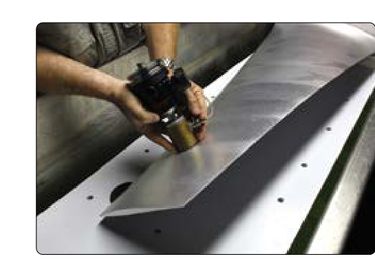
When an aircraft maintenance technician needs to verify the internal integrity of a structural component — a wing spar, a turbine disk, a landing gear strut — removing and sectioning the part is rarely an option. Ultrasonic inspection is one of the most powerful nondestructive testing (NDT) methods available precisely because it reveals hidden cracks, voids, delaminations, and inclusions without altering or destroying the part being examined. Understanding how ultrasound behaves in solid materials, which techniques apply to which situations, and how to interpret the resulting data is essential knowledge for any AMT pursuing general certification and, more importantly, for anyone responsible for keeping aircraft airworthy.
Ultrasonic inspection is grounded in the physics of sound wave propagation through solid matter. Unlike the audible range of human hearing (roughly 20 Hz to 20,000 Hz), ultrasonic testing uses frequencies typically between 0.5 MHz and 25 MHz for aviation applications. At these frequencies, sound travels through metals, composites, and other structural materials in predictable ways, reflecting or scattering whenever it encounters a change in acoustic impedance — that is, whenever it crosses a boundary between materials of different density and stiffness. A crack filled with air presents an enormous acoustic impedance mismatch compared to solid aluminum, causing a strong echo that the technician can detect and measure.
The Physics Behind Ultrasonic Propagation
Sound waves used in ultrasonic inspection travel through solid materials in several modes, each useful for different inspection geometries. Longitudinal (compression) waves cause material particles to vibrate back and forth along the direction of wave travel. These are the most commonly used waves in straight-beam inspections and propagate efficiently through most solid materials. Shear (transverse) waves cause particles to vibrate perpendicular to the direction of travel; shear waves cannot propagate through liquids, but the reason they are used in angle-beam techniques is that mode conversion at an angled interface (via a wedge) converts the incident longitudinal wave into a refracted shear wave traveling at a controlled angle inside the solid, which is useful for detecting flaws oriented off-axis from the surface. Surface (Rayleigh) waves travel along the surface of a material to an effective depth of roughly one wavelength (sources vary somewhat, with some describing useful penetration extending to about one to one-and-a-half wavelengths) and are excellent for detecting surface-breaking or near-surface defects in curved or contoured parts. Lamb waves (plate waves) propagate through thin sheet material and can survey large areas rapidly.
The ultrasonic transducer — commonly called a probe — converts electrical energy into mechanical vibration using the piezoelectric effect. A piezoelectric crystal (historically quartz, now more often lead zirconate titanate) vibrates at its natural resonant frequency when excited by a voltage pulse from the test instrument. The same crystal then acts as a receiver: returning echoes deform it slightly, generating a voltage signal that the instrument amplifies and displays. This dual send-receive role makes the technique highly sensitive and compact.
Primary Inspection Techniques
Pulse-Echo Method
The pulse-echo technique is the most widely used approach in aviation NDT. A single transducer sends a brief burst of ultrasonic energy into the part and then listens for returning echoes during the interval between pulses. The instrument displays amplitude (signal strength) on the vertical axis and time-of-flight (which correlates to depth) on the horizontal axis — a display called an A-scan. When the technician couples the transducer to a smooth, flat surface on a defect-free part, only two main signals appear: the initial pulse (the transmitted burst) on the left side of the screen and the back-wall echo (the reflection from the far surface) on the right. Any discontinuity between the front and back surfaces creates an additional echo that appears between these two signals. The depth and size of the reflector can be estimated from the position and amplitude of this intermediate echo. Pulse-echo works excellently when only one side of the part is accessible.
Through-Transmission Method
In through-transmission testing, two separate transducers are positioned on opposite sides of the component — one as a sender, one as a receiver. Because the technique measures the total attenuation of the signal as it travels across the part rather than listening for echoes, it excels at detecting disbonds and delaminations in composite laminates that tend to scatter rather than reflect sound cleanly. The limitation is that both sides of the part must be accessible and that through-transmission gives no direct indication of defect depth — only that a defect exists somewhere along the beam path. This method is especially common in composite structure inspection on modern aircraft.
Angle-Beam Technique
Straight-beam inspection sends sound perpendicular to the surface, making it well-suited for detecting flaws oriented parallel to the surface (like a delamination or a void). However, cracks in welds and around fastener holes are often oriented perpendicular or at an angle to the surface. The angle-beam technique uses a wedge-shaped shoe attached to the transducer to refract sound into the material at a controlled angle — commonly 45°, 60°, or 70° — converting longitudinal waves into shear waves inside the part. The refracted shear beam travels diagonally, bouncing off the back wall and sweeping through the material. A crack oriented perpendicular to the surface intercepts this angled beam and returns a strong echo. Angle-beam inspection of welds, spars, and structural fittings is a routine NDT task at certified repair stations.
Immersion Testing
In immersion testing, both the transducer and the part are submerged in a water tank (or water is squirted between the probe and the part in a squirter system). Water serves as the coupling medium, providing very consistent acoustic contact across complex curved surfaces. Automated immersion systems can scan large panels — composite wing skins, for example — with a mechanized scanner that records amplitude data point by point. The result is a C-scan, a two-dimensional color-coded map of the part that makes delaminations and voids immediately visible to the eye. This technique is extensively used in manufacturing quality control and heavy maintenance.
Couplants: Why They Matter
Air is an extremely poor acoustic coupler — the mismatch between the transducer face and an air gap reflects virtually all ultrasonic energy before it can enter the part. A couplant is a liquid or gel (water, glycerin, commercial gel, or light oil) applied between the probe and the part surface to eliminate the air gap and allow efficient energy transfer. The choice of couplant matters: it must be compatible with the part material (some oils can damage composites or certain coatings), and it must be thoroughly removed after inspection if it could corrode or contaminate aircraft systems. The Aviation Maintenance Technician Handbook — General (FAA-H-8083-30) specifies that couplant selection and removal are part of the technician's procedural responsibility.
Why Ultrasonic Inspection Matters for Airworthiness
Many critical aircraft components are made of materials — high-strength aluminum alloys, titanium, steel, and composite laminates — that can harbor fatigue cracks or manufacturing defects invisible to visual inspection or even radiography. Turbine disk bores, compressor blade roots, spar caps, and nacelle attach fittings all experience cyclic loading that can initiate subsurface cracks long before any surface indication appears. Ultrasonic testing can detect a fatigue crack only a few millimeters in length deep inside a part, giving maintenance programs the opportunity to remove or repair the component before it reaches a critical size. Continued Airworthiness instructions in Airworthiness Directives and Maintenance Review Boards frequently specify ultrasonic inspection intervals for life-limited and fatigue-critical parts.
Key Numbers and Rules
- Frequency range: Aviation ultrasonic testing typically uses 0.5 MHz to 25 MHz; higher frequencies provide better resolution but less penetration depth.
- Calibration standards: The technician must calibrate the instrument using a reference standard (calibration block) made from the same or acoustically equivalent material as the part being inspected, with known artificial defects (flat-bottom holes, side-drilled holes, or notches).
- Signal-to-noise ratio: A defect indication must be distinguishable from background noise; specific amplitude or signal-to-noise acceptance thresholds are set by the applicable procedure or industry specification (such as NAS 410 or an OEM NDT manual) rather than a single fixed FAA-mandated percentage.
- Access requirement: Pulse-echo requires access to one surface only; through-transmission and immersion scanning require access to both surfaces.
- Personnel qualification: AC 43.13-1B and FAA-H-8083-30 discuss the need for technicians performing NDT to be qualified for the task; specific certification levels (such as those under NAS 410 or SNT-TC-1A) are industry-adopted standards commonly referenced in practice rather than an FAA-mandated certification scheme.
- Documentation: All ultrasonic inspections must be documented in the aircraft maintenance record per 14 CFR Part 43, including the method used, equipment, calibration standard, and results.
Common Test Traps
- Confusing pulse-echo with through-transmission: Pulse-echo uses a single transducer and detects echoes; through-transmission uses two transducers and detects signal loss. Mixing up which method requires one-sided versus two-sided access is a frequent exam error.
- Forgetting the couplant's role: Test questions sometimes ask why a couplant is used. The answer is to eliminate the air gap and improve acoustic energy transfer — not to lubricate the probe or protect the surface.
- Misidentifying the A-scan display: The initial pulse (left) and back-wall echo (right) are always present on a good part. An intermediate indication between them signals a discontinuity. Students sometimes call the back-wall echo a defect indication.
- Assuming ultrasound detects all crack orientations equally: A straight-beam probe is most sensitive to reflectors oriented perpendicular to the beam's direction of travel — since the beam travels straight down into the part, this means flaws lying parallel to the entry surface (i.e., horizontal, laminar-type defects). Cracks perpendicular to the surface require angle-beam techniques. Selecting the wrong technique can result in a missed defect.
- Overlooking calibration requirements: The instrument must be calibrated with a reference standard made from the same or equivalent material before each inspection session. Using an incorrect calibration block invalidates the inspection results entirely.