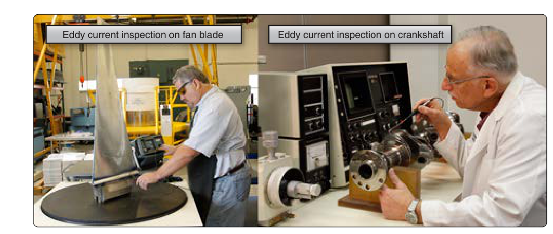
Eddy current inspection is one of the most widely used non-destructive testing (NDT) methods in aviation maintenance. Unlike visual inspection or dye penetrant testing, eddy current can detect flaws hidden beneath the surface without any disassembly or surface preparation in many cases. For aviation maintenance technicians (AMTs), a solid understanding of how eddy currents are generated, how flaws alter them, and how to interpret the results is essential—both for the FAA AMT General Knowledge Test and for real shop floor practice.
The technique works exclusively on electrically conductive materials, which makes it ideal for the aluminum alloys, titanium, and certain steels that make up the vast majority of modern aircraft structures. It can find cracks, corrosion, heat damage, and even measure coating thickness—all without cutting, grinding, or chemically treating the part.
The Physics Behind Eddy Currents
Eddy currents are closed loops of electrical current induced in a conductive material when it is exposed to a changing magnetic field. The source of that changing field is an alternating current (AC) flowing through an inspection coil (also called a probe coil or test coil). As AC cycles through the coil, the magnetic field it produces constantly expands and collapses. When a conductive test piece is brought close to the coil, this changing field induces voltage in the material by Faraday's Law of Electromagnetic Induction. Because the material is a conductor with a closed electrical path, that induced voltage drives circulating currents—eddy currents—flowing in circular patterns perpendicular to the magnetic field lines.
Those eddy currents, in turn, create their own magnetic field that opposes the coil's field (by Lenz's Law). This opposition is measurable: it changes the electrical impedance of the probe coil. The eddy current instrument monitors the coil's impedance continuously. When a flaw, dimensional change, or material property difference disrupts the normal eddy current flow, the impedance changes in a characteristic way, and the instrument displays that change for the technician to interpret.
Factors That Influence Eddy Current Response
Several material and instrument variables determine how effectively eddy currents can detect a given flaw:
- Conductivity: Different alloys have different electrical conductivities. A change in conductivity—caused by heat damage, incorrect alloy, or corrosion—alters eddy current flow and is detectable. Eddy current instruments can actually measure conductivity in units of percent IACS (International Annealed Copper Standard).
- Permeability: Magnetic permeability affects how easily a magnetic field penetrates a material. Ferromagnetic materials (like carbon steel) have high permeability, which can overwhelm the eddy current signal and make interpretation difficult. That is why eddy current inspection is far more commonly applied to non-ferromagnetic metals in aviation.
- Frequency: The frequency of the AC driving the coil is one of the most important controls the technician has. Higher frequencies produce eddy currents that concentrate near the surface (the skin effect), giving excellent sensitivity to surface cracks but little penetration depth. Lower frequencies allow deeper penetration, useful for detecting subsurface corrosion or flaws beneath fasteners. Choosing the right frequency for the inspection task is critical.
- Skin Depth (Standard Depth of Penetration): The depth at which eddy current density falls to about 37 percent of its surface value is called the standard depth of penetration (or skin depth). It decreases with increasing frequency, increasing conductivity, and increasing permeability. This is why technicians dial in frequency carefully: too high and you miss buried flaws; too low and surface sensitivity suffers.
- Lift-off: The gap between the probe and the test surface is called lift-off. Even small variations in lift-off—caused by surface roughness, paint, or probe wobble—can create strong, unwanted signals that mask flaw indications. Good probe-handling technique minimizes lift-off variation.
- Edge Effect: When the probe nears the physical edge of a part, the geometry of the eddy current field changes abruptly, producing a large signal unrelated to flaws. Technicians must be aware of edge boundaries and account for this in their scanning pattern.
Types of Eddy Current Probes
Different probe geometries are optimized for different inspection tasks:
- Surface (pancake) probes: Flat coil wound to scan flat or slightly curved surfaces. Most common for general surface crack detection.
- Encircling (feed-through) probes: The test piece passes through or is surrounded by the coil. Used for inspecting rods, tubes, or fastener shanks rapidly in production settings.
- Bolt-hole probes (rotating probes): Inserted into fastener holes and rotated to scan the entire bore. Extremely common in aviation for detecting fatigue cracks radiating from fastener holes in wing skins and fuselage frames—a very high-stress location.
- Differential probes: Contain two coils wired to oppose each other. Gradual changes (like a slow taper) cancel out, while abrupt discontinuities (cracks) produce a strong signal. They are less sensitive to lift-off and temperature drift, making them ideal for production scanning.
- Absolute probes: A single coil compared to a reference. More sensitive to gradual changes like corrosion thinning or conductivity shifts.
Aviation Applications
Eddy current inspection is embedded throughout aviation maintenance and manufacturing inspection programs. Common applications include:
- Detecting fatigue cracks around fastener holes in aluminum wing skins, fuselage frames, and bulkheads—often the first location a crack initiates under cyclic loading.
- Inspecting turbine engine components such as disk bores, blade attachment slots, and compressor blades for surface cracks—particularly after a hard landing, bird strike, or foreign-object damage event.
- Measuring the thickness of anodize coatings, paint, or non-conductive coatings over aluminum using lift-off response characteristics.
- Verifying alloy identification when mixed-material risk exists on a repair, since different alloys have measurably different conductivities.
- Detecting corrosion thinning in multi-layer aircraft structures (using low-frequency techniques to reach second and third layers).
Reading the Display: Impedance Plane
Most modern eddy current instruments display results on an impedance plane—a two-axis graph where the horizontal axis represents resistance and the vertical axis represents inductive reactance. A flaw-free reference produces a single baseline point or a predictable trace. As the probe scans over a crack, the operating point moves away from the baseline in a characteristic direction and magnitude. Lift-off changes produce their own characteristic trace direction, which is usually distinguishable from crack signals once the technician is trained. Some portable instruments simplify this to a bar graph or audio alarm, but understanding the impedance plane is fundamental for interpreting complex or ambiguous indications.
Key Numbers and Rules
- Eddy current works only on electrically conductive materials; it cannot be used on wood, composites, or plastics.
- Sensitivity is highest at the surface and decreases exponentially with depth—practical flaw detection is generally limited to within a few millimeters depending on frequency and conductivity.
- Higher AC frequency = shallower penetration (better surface sensitivity); lower frequency = deeper penetration (better subsurface sensitivity).
- Lift-off must be minimized and held constant for reliable, repeatable results—probe wobble is a common source of false indications.
- Reference standards (calibration standards) with known artificial defects of specified depth must be used to set instrument sensitivity before each inspection, as required by the applicable maintenance manual or NDT procedure.
- Eddy current inspection must always be performed by appropriately trained and, where required, certificated NDT personnel following an approved procedure—NDT personnel qualification for aviation maintenance is generally established by the repair station's or operator's approved procedures and industry standards such as NAS 410, rather than by 14 CFR Part 65, which addresses certification of mechanics, repairmen, parachute riggers, dispatchers, and air traffic control tower operators.
Memory Aid
To remember the key variables that affect eddy current response, many instructors use the phrase "CLEF": Conductivity, Lift-off, Eddy current frequency, and Flaws (or geometry). Every time a signal changes on the impedance plane, ask yourself which of these four factors caused it. This framework helps technicians separate real flaw indications from instrument artifacts.
Common Test Traps
- Thinking eddy current works on all metals equally: Ferromagnetic materials like carbon steel are difficult to inspect because high permeability dominates the signal; eddy current is primarily used on non-ferromagnetic metals in aviation practice.
- Confusing frequency and depth: Test questions may try to get you to say higher frequency means deeper penetration—it does not. Higher frequency means shallower penetration due to the skin effect.
- Overlooking lift-off as a source of false signals: Students sometimes assume any impedance change means a crack. Lift-off variation is one of the most common sources of misleading signals and must be controlled or balanced out.
- Assuming no surface prep is ever needed: While eddy current requires less preparation than dye penetrant, loose scale, heavy grease, or ferromagnetic contamination on the surface can still interfere with the probe coupling and mask real defects.
- Skipping calibration with a reference standard: The instrument must be calibrated against an appropriate reference standard before each inspection session. Jumping straight to scanning without calibration is a procedural violation that can result in missed flaws—and is specifically addressed in all NDT procedures approved under the maintenance program.