Every aircraft electrical system faces two fundamental challenges: keeping the output voltage steady across a wide range of engine speeds and electrical loads, and preventing excessive current from destroying wires, components, and the generator or alternator itself. Two devices sit at the heart of solving these problems — the voltage regulator and the current limiter. Understanding how each device works, why it is necessary, and how the two interact is essential knowledge for any Aviation Maintenance Technician (AMT) working on airframe electrical systems, and it forms a core topic on the FAA Airframe Knowledge Test.
Aircraft generators and alternators are inherently variable sources of electrical power. As engine RPM rises and falls, and as pilots switch avionics, lights, and other loads on and off, an unregulated system would see voltage swings that could damage sensitive avionics, dim or over-brighten lighting, and shorten the life of every component on the bus. The regulator and limiter work together to transform a raw, variable source into a stable, safe supply.
How Voltage Regulators Work
A voltage regulator controls the output voltage of a generator or alternator by adjusting the strength of the magnetic field inside the machine. In a DC generator, current flows through a set of field windings to create the magnetic field that induces voltage in the rotating armature. The regulator monitors bus voltage and continuously varies the current through the field windings to keep output at the design value — typically 14 volts in a 12-volt system or 28 volts in a 24-volt system.
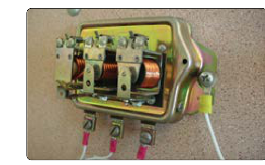
The most common type found on older light aircraft is the vibrating-contact (or carbon-pile) voltage regulator. In a vibrating-contact design, a set of contact points opens and closes rapidly — many times per second — to insert resistance into the field circuit when voltage rises above the set point. When voltage drops, the contacts close and allow full field current to restore output. The average field current is therefore modulated by the duty cycle of these contacts, keeping voltage within a narrow band.
A carbon-pile regulator uses a stack of carbon discs whose resistance changes as a solenoid-controlled spring varies the pressure on the pile. More spring pressure compresses the discs, lowering resistance, increasing field current, and raising output. Less pressure does the opposite. Carbon-pile regulators are smooth and continuous in operation rather than switching on and off, making them well suited to larger aircraft generators.
Modern light aircraft equipped with AC alternators typically use solid-state electronic regulators built from transistors and integrated circuits. These devices have no moving parts and sense output voltage electronically, making tiny, rapid corrections to field current through transistor switching. They are more reliable, more precise, and require less maintenance than their mechanical predecessors. Many are sealed units replaced as a complete assembly during maintenance.
In an alternator system, the voltage regulator performs the same fundamental job — it controls the field current of the alternator's rotor winding to hold the rectified DC bus voltage at the design level. Because alternator output depends on field excitation rather than mechanical commutation, the solid-state regulator can control output smoothly from idle to redline RPM.
How Current Limiters Work
A current limiter is a protective device that prevents the generator or alternator from being overloaded by excessive current demand. While a voltage regulator controls the quality of the output, the current limiter controls the quantity. Without a current limiter, a heavy electrical load — or a short circuit somewhere on the bus — could force the generator or alternator to produce more current than it is designed to handle, resulting in overheating, burned windings, or a fire.
In DC generator systems, the current limiter is usually a separate element within the generator control unit. It works by monitoring generator output current and, when that current exceeds the rated limit, reducing field excitation to drop output. This is sometimes called a current limiter relay or an equalizer circuit in parallel generator installations. The effect is that the generator effectively folds back its output rather than sustaining an overload condition.
In many light aircraft alternator systems, current limiting is accomplished not by a separate relay but by the inherent design of the alternator itself. Because an alternator's maximum current output is limited by its magnetic saturation characteristics, it is naturally self-limiting — it cannot produce more than its rated output no matter how low the load impedance becomes. This is one of the key practical advantages alternators have over DC generators in light aircraft.
Larger and more complex aircraft use current limiters (sometimes called fusible current limiters or thermal limiters) that are essentially heavy-duty fuses installed in the main feeder lines between the generator and the bus. These are rated for high continuous current — often hundreds of amperes — and open only in a true overload condition, protecting the main feeder cables from fire. Unlike circuit breakers, fusible current limiters are not intended for routine protection of individual loads; that job belongs to circuit breakers or fuses on each branch circuit.
Parallel Generator Systems and Load Sharing
Many twin-engine and turbine-powered aircraft operate two or more generators in parallel on a common bus. In this configuration, it is essential that each generator carries an equal share of the electrical load. If one generator tries to supply more than its share, it will overheat; if it tries to supply less, the other generator is overloaded. An equalizer circuit — sometimes called a parallel circuit — compares the load on each generator and adjusts their field currents to keep load sharing balanced. The voltage regulators of each generator communicate through the equalizer so that no single machine dominates the bus. Understanding this interaction is important for AMTs troubleshooting generator imbalance faults on multi-engine airframes.
Why These Devices Matter for Safety and Airworthiness
A failed or maladjusted voltage regulator can produce two dangerous outcomes. Overvoltage — where the regulator fails in a way that allows uncontrolled field current — can drive bus voltage well above the design value, destroying avionics, burning out light bulbs en masse, and potentially damaging the battery. Most modern aircraft include an overvoltage relay (or crowbar circuit) that automatically disconnects the alternator from the bus if output voltage exceeds a threshold (typically around 31–32 volts on a 28-volt system). Undervoltage — where the regulator reduces field current too aggressively — causes the battery to discharge as it tries to support the bus alone, eventually leading to total electrical failure.
A failed current limiter in a generator system can allow sustained overcurrent to flow through generator windings, feeder cables, and bus components, creating a serious fire risk. AMTs must verify that current limiters and overvoltage protection are correctly installed, rated for the aircraft, and functional as part of any electrical system inspection or troubleshooting procedure.
Key Numbers and Rules
- Nominal system voltages: 14V for 12V systems, 28V for 24V systems — the regulator maintains these values under normal load.
- Overvoltage disconnect: Many 28-volt systems disconnect the alternator automatically at approximately 31–32 volts to protect equipment.
- Alternator self-limiting: Unlike DC generators, alternators cannot be forced to produce current beyond their rated maximum due to magnetic saturation — a key exam point.
- Fusible current limiters: Installed in main feeder lines on larger aircraft; rated in hundreds of amperes; not resettable — they must be replaced when opened.
- Load sharing: Parallel generator systems require equalizer circuits to distribute electrical load evenly across all generators.
- Regulatory basis: Aircraft electrical systems must comply with 14 CFR Part 23 (small airplanes) or Part 25 (transport category) airworthiness standards, which specify voltage regulation and overcurrent protection requirements.
Common Test Traps
- Confusing the regulator's function with the limiter's function. The voltage regulator controls output voltage by varying field current; the current limiter prevents overcurrent damage to the generator and wiring. They are separate functions, though sometimes integrated in one control unit.
- Assuming alternators need current limiters the same way generators do. Because alternators are inherently self-limiting due to magnetic saturation, they do not require a separate current limiter relay the way DC generators do. The FAA test frequently exploits this distinction.
- Mixing up carbon-pile and vibrating-contact regulators. Carbon-pile regulators vary resistance continuously through mechanical pressure; vibrating-contact regulators switch contacts rapidly. Know which aircraft types use which design.
- Forgetting the overvoltage relay. Many students remember the voltage regulator but forget that a separate overvoltage protection relay is needed to disconnect the alternator from the bus if the regulator itself fails high.
- Misunderstanding parallel system equalizer circuits. The equalizer does not equalize voltage — it equalizes current load. Bus voltage is still governed by each generator's voltage regulator. Confusing these two functions is a classic trap on multi-engine electrical system questions.