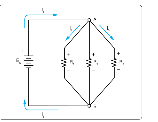
Every wire, relay, and electronic box in an aircraft obeys two elegant rules formulated by German physicist Gustav Kirchhoff. Kirchhoff's Voltage Law (KVL) and Kirchhoff's Current Law (KCL) are not abstract theory — they are the practical tools an Aviation Maintenance Technician (AMT) uses to predict voltages, trace fault currents, and verify that a repaired circuit will behave correctly before the aircraft returns to service. Ohm's Law tells you how a single resistor behaves; Kirchhoff's Laws tell you how an entire network of resistors, loads, and sources behaves together. Mastering these two laws is essential for the FAA AMT General knowledge test and for real shop troubleshooting.
Kirchhoff's Current Law (KCL) — The Junction Rule
Kirchhoff's Current Law states that the algebraic sum of all currents entering and leaving any junction (node) in a circuit equals zero. Put plainly: all the current that flows into a point must flow out of that same point. Electrons do not pile up or disappear at a junction — they are conserved.
Think of a water pipe that splits into two smaller pipes. Every gallon per minute entering the split must leave through one branch or the other. Electricity behaves identically. If 10 amperes flow into a node, and two branches leave that node, the branch currents must add up to exactly 10 amperes — perhaps 6 A in one branch and 4 A in the other.
Mathematically, if we call currents entering the node positive and currents leaving negative: Iin1 + Iin2 − Iout1 − Iout2 = 0. The choice of sign convention is arbitrary as long as you are consistent throughout the problem.
KCL in a Parallel Circuit
Parallel circuits are the most common application of KCL in aircraft wiring. Each load (landing light, avionics box, motor) is connected directly across the bus voltage, and each draws its own independent current. The total current drawn from the bus equals the sum of all branch currents. This is why adding more loads to an aircraft bus increases the total amperage demand on the generator — each new parallel branch adds its own current draw to the total.
For example, imagine an aircraft bus feeding three parallel loads: a 2 A position light circuit, a 5 A landing light, and a 3 A fuel pump. KCL tells us the bus must supply 2 + 5 + 3 = 10 A total. If a current-limiting fuse on the bus is rated at 8 A, it will blow — a real troubleshooting scenario that KCL helps diagnose before you even pick up a meter.
Kirchhoff's Voltage Law (KVL) — The Loop Rule
Kirchhoff's Voltage Law states that the algebraic sum of all voltage rises and voltage drops around any closed loop in a circuit equals zero. In other words, the energy supplied by the source in a loop is exactly consumed by the loads in that same loop — no more, no less.
Imagine tracing a path around a complete circuit loop, starting and ending at the same point. Every time you cross a source (battery or generator) in the direction of conventional current flow, you gain voltage (a rise). Every time you cross a resistor or load, you lose voltage (a drop). When you arrive back at your starting point, your net voltage change is exactly zero — you have climbed as much voltage as you descended.
KVL in a Series Circuit
In a series circuit, the same current flows through every component, and KVL tells us that the sum of all voltage drops across the resistors equals the source voltage. If a 28-volt aircraft bus feeds three series resistors of 4 Ω, 6 Ω, and 4 Ω, the total resistance is 14 Ω, the current is 28 V ÷ 14 Ω = 2 A, and the voltage drops are 8 V, 12 V, and 8 V respectively — summing to exactly 28 V. This confirms KVL: 8 + 12 + 8 = 28 V, and 28 V (source rise) − 28 V (total drop) = 0.
Voltage Drop and Aircraft Wiring
KVL has a critically important practical consequence for AMTs: every bit of resistance in a circuit — including wire resistance, connector resistance, and switch contact resistance — drops voltage. That voltage is subtracted from what the load actually receives. FAA guidance specifies maximum allowable voltage drops in aircraft wiring systems because excessive resistance in wiring means the load (motor, avionics, light) operates at a lower-than-intended voltage, reducing performance or causing malfunction. KVL is the law that explains exactly why voltage drop matters: if the wire eats 2 V out of a 14 V system, the load only sees 12 V.
Applying Both Laws Together — Complex Circuit Analysis
Real aircraft circuits are neither purely series nor purely parallel — they contain combinations of both. KVL and KCL are used together to write a system of equations and solve for unknown currents and voltages. The general approach is:
- Identify all nodes (junctions) and assign unknown current variables to each branch.
- Apply KCL at each node to write equations relating branch currents.
- Identify all independent loops and apply KVL around each loop, writing equations for voltage rises and drops.
- Solve the system of equations algebraically for the unknown currents or voltages.
For the AMT knowledge test, problems rarely require solving a large simultaneous system. More commonly, you will apply one law at a time to a clearly series or clearly parallel portion of a circuit. However, understanding the combined method is essential for interpreting wiring diagrams and for justifying why a circuit behaves the way it does during troubleshooting.
Why These Laws Matter for Aircraft Maintenance
Kirchhoff's Laws underpin every electrical task an AMT performs. When you measure voltage at a load and find it lower than bus voltage, KVL tells you the missing voltage is being dropped somewhere upstream — a corroded connector, a chafed wire with high resistance, or a marginal switch contact. You can then use a voltmeter to probe around the loop, measuring drops across each segment, until the offending component is found. This technique, sometimes called voltage drop testing, is a direct application of KVL.
Similarly, when you suspect a short circuit in a parallel branch has tripped a circuit breaker, KCL explains the problem: the shorted branch drew excessive current, the node current exceeded the breaker rating, and the breaker opened to protect the bus and wiring. Without understanding KCL, the relationship between a shorted branch and total bus current would be mysterious.
KVL and KCL also underlie the design of current measurement instruments. An ammeter is placed in series within a branch because series placement ensures all of that branch's current flows through the meter — a direct application of KCL. A voltmeter is placed in parallel across a component because KVL guarantees the voltage across the parallel voltmeter equals the voltage across the component.
Key Numbers and Rules
- KCL (junction rule): Sum of all currents at any node = 0. Currents in = Currents out.
- KVL (loop rule): Sum of all voltage rises and drops around any closed loop = 0. Source voltage = sum of load voltage drops.
- Series circuits: Same current everywhere; voltages add to equal source voltage (KVL).
- Parallel circuits: Same voltage across all branches; branch currents add to equal total current (KCL).
- Voltage drop in aircraft wiring: Excessive wire or connector resistance violates acceptable voltage budget — KVL quantifies exactly how much voltage the load loses.
- Instrument placement: Ammeters in series (KCL); voltmeters in parallel (KVL).
- Sign convention: Entering currents and voltage rises are typically assigned positive; leaving currents and voltage drops are negative. Consistency is mandatory — mixing conventions will produce wrong answers.
Common Test Traps
- Forgetting wire resistance in KVL problems. Test questions sometimes include internal resistance of a battery or resistance of the supply wire. Students who ignore these and use only the load resistances will calculate the wrong voltage drop across the load. Every resistive element in the loop must be included.
- Confusing KCL with total current in series circuits. In a series circuit there are no junctions, so KCL does not produce different branch currents — the same current flows everywhere. Trying to add currents in a series loop is a common error.
- Sign errors when applying KVL. If you trace a loop opposite to the assumed current direction through a resistor, that element's voltage drop must be entered as a rise in your equation. Careless sign handling is the single most common math error in KVL problems.
- Assuming voltage is the same at every node. Voltage is only equal across components that share the same two nodes (true parallel). If there is any resistance between two nodes — even just wire resistance — KVL guarantees a voltage difference exists.
- Misidentifying series vs. parallel configuration. A branch that appears parallel on a schematic may be series with a switch or fuse. Always trace the actual current path before applying either law.