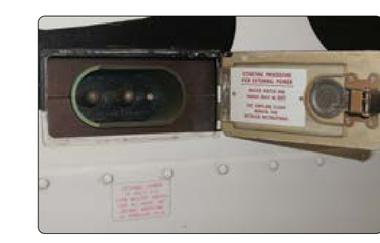
Ground power units (GPUs) are a staple of modern maintenance and line operations. Rather than starting an engine or auxiliary power unit (APU) to power avionics, lighting, or hydraulic systems during ground servicing, technicians connect a GPU to the aircraft's external power receptacle — a dedicated interface built into the airframe specifically for this purpose. Done correctly, GPU hookup is efficient and safe. Done incorrectly, it can destroy avionics, weld contactors, or injure personnel. This article walks through the design, standards, sequencing, and real-world best practices that an Aviation Maintenance Technician (AMT) must know.
The topic falls squarely within the aircraft electrical systems subject area tested on the FAA Airframe Knowledge Exam and covered in the Aviation Maintenance Technician Handbook – Airframe (FAA-H-8083-31). The underlying physics are grounded in the Aviation Maintenance Technician Handbook – General (FAA-H-8083-30), which covers DC circuit fundamentals, polarity conventions, and bus architecture that make GPU hookup procedures make sense.
What Is an External Power Receptacle?
An external power receptacle (sometimes called a ground power plug or external power port) is a standardized electrical connector installed in the aircraft skin — typically near the nose gear bay, forward fuselage, or wing root — that provides a direct electrical path to the aircraft's main DC or AC bus. The receptacle is wired through an external power contactor (relay) and, on sophisticated aircraft, through a bus protection relay or external power control unit (EPCU) that monitors the quality of the incoming power before allowing it onto the bus.
On most transport-category and many general aviation aircraft, the external DC receptacle follows the MS3509 standard (or the newer MIL-DTL-83413 style connector), which defines a three-pin configuration. The standard configuration for 28-volt DC aircraft uses three pins: positive, negative, and a third polarity/ground pin used to help prevent contactor closure when the GPU is connected with reversed polarity. Because aircraft electrical systems are predominantly negative-ground (airframe is the negative return), polarity at the receptacle is critical. Reversing polarity — even momentarily — can instantly damage diodes, transistors, and solid-state avionics on the bus.
Types of Ground Power Units
GPUs come in two broad categories based on aircraft electrical architecture:
- DC GPUs (28 V DC): Used for piston and turboprop general aviation aircraft, as well as many military jets. Output is typically 28 volts DC at current ratings ranging from 200 to 1,500 amperes depending on the aircraft's load requirements. The GPU must be capable of supplying surge current for avionics initialization without voltage droop below approximately 22 volts.
- AC GPUs (115/200 V AC, 400 Hz): Used for transport-category jets and turbofan aircraft whose primary bus is AC. The 400 Hz frequency (rather than utility-grid 60 Hz) allows smaller, lighter transformers throughout the aircraft. GPU output must be 115 V AC (line-to-neutral) / 200 V AC (line-to-line) at 400 Hz, three-phase. Voltage tolerance is typically within ±2% and frequency within ±1% of nominal during steady-state operation.
Some aircraft (particularly modern transport jets with APUs) can also accept external AC power through a three-phase four-wire connector conforming to the ARINC or ISO standards referenced in the aircraft's maintenance manual. Always consult the specific Aircraft Maintenance Manual (AMM) chapter for the applicable power specification.
The External Power Contactor and Bus Protection
A key safety component between the receptacle and the bus is the external power contactor. This heavy-duty relay does not close automatically when a GPU is plugged in; it closes only when the flight crew or technician selects external power via a cockpit switch (or on some aircraft, a ground service panel switch). This design prevents inadvertent bus energization.
On more advanced aircraft, an External Power Control Unit (EPCU) or equivalent bus protection circuitry monitors the GPU's output for correct voltage, frequency (on AC systems), phase rotation, and phasing before allowing the contactor to close. If any parameter is out of tolerance, the EPCU inhibits contactor closure and may illuminate a fault light. This is why a GPU that appears to be running may still not power the aircraft — the EPCU has rejected the power quality. The technician should verify GPU output with a calibrated meter before concluding the aircraft system is at fault.
Step-by-Step GPU Hookup Procedure
The following general procedure reflects standard industry practice consistent with FAA-H-8083-31 guidance and typical AMM procedures. Always supersede these steps with the aircraft-specific AMM:
- Pre-connection inspection: Inspect the GPU cable, connector pins, and the aircraft receptacle for corrosion, bent pins, damaged insulation, and debris. A corroded or damaged connector increases resistance, causing voltage drop and heat generation under load.
- Verify GPU output before connection: Set the GPU output and measure voltage (and frequency/phase on AC units) at the GPU output terminals with a calibrated multimeter or power quality meter. Confirm values are within AMM-specified limits before plugging in.
- Position the GPU safely: Place the GPU unit on solid, level ground clear of aircraft control surfaces, landing gear doors, and prop/rotor arcs. Ensure the GPU exhaust (if engine-driven) is directed away from the aircraft and personnel.
- Connect the GPU cable to the aircraft receptacle: For DC systems, verify positive-to-positive pin alignment before seating the connector. For AC systems, verify phase rotation if the aircraft's documentation requires it. Seat the connector fully and engage any locking collar or safety pin.
- Start/activate the GPU: Bring the GPU online and observe output voltage on the GPU's panel meter. Do not yet close the aircraft's external power contactor.
- Verify aircraft-side readiness: Confirm all required circuit breakers are set and cockpit switches are positioned per the AMM before selecting external power ON.
- Select external power ON: On the cockpit external power panel or ground service panel, close the external power contactor. Observe bus voltage and ammeter (if installed) for normal indications. On AC aircraft, confirm all three phases are present.
- Perform required maintenance tasks: With the bus energized, perform avionics tests, system checks, or maintenance as required.
Disconnection Sequence — Order Matters
The disconnect sequence is as important as the hookup sequence. Incorrect disconnection can cause voltage spikes that damage avionics. The correct sequence is generally:
- De-energize or shut down all aircraft systems drawing power from the external bus.
- Open (turn OFF) the external power contactor from the cockpit or ground panel — this breaks the circuit before the physical connector is disturbed.
- Shut down the GPU.
- Disconnect the GPU cable from the aircraft receptacle and stow the cable.
The critical rule: break the circuit electrically before breaking it mechanically. Pulling a live, loaded connector under current produces an arc at the pins that erodes contact surfaces and can weld pins in the mating receptacle — a finding that generates a maintenance write-up and connector replacement.
Why This Matters: Safety and Airworthiness Implications
Incorrect GPU procedures are a documented cause of avionics damage in maintenance environments. Reversed polarity on a 28 V DC system can instantly forward-bias protection diodes to destruction and damage microprocessors on the avionics bus. Overvoltage (a GPU with a faulty voltage regulator) can stress capacitors and semiconductor junctions across dozens of Line Replaceable Units (LRUs). Overcurrent from a GPU that cannot sustain voltage under load causes brownout conditions that corrupt avionics memory and can force complete re-initialization or software reloads — expensive and time-consuming.
From a regulatory standpoint, any maintenance action that results in damage to aircraft components must be documented and corrected before return to service under 14 CFR Part 43. A technician who improperly connects ground power and damages avionics has potentially created an unairworthy condition that must be disclosed in the aircraft maintenance records. The responsible technician completes the appropriate maintenance record entry and ensures corrective action before signing the aircraft off.
Key Numbers and Rules
- 28 V DC nominal: Standard DC bus voltage for most general aviation and military aircraft; GPU must maintain this within roughly ±1 V under steady load.
- 115/200 V AC, 400 Hz: Standard for transport-category AC buses; frequency tolerance typically ±1%, voltage ±2% steady-state.
- Phase rotation: On AC aircraft, incorrect phase rotation causes three-phase motors and certain equipment to run in reverse — always verify rotation matches AMM specification.
- Break circuit before connector: Open the contactor/switch before physically unplugging the GPU cable under any load.
- Consult the AMM: Every specific voltage limit, connector torque, and sequencing step is aircraft-specific; the AMM governs all GPU procedures.
Common Test Traps
- Assuming DC polarity is self-correcting: Aircraft DC systems are NOT polarity-tolerant. Reversed polarity, even briefly, can destroy solid-state components. The FAA exam may ask why polarity matters — the answer is protection of unidirectional semiconductor devices on the bus.
- Confusing 60 Hz with 400 Hz: A standard utility-grid GPU running at 60 Hz cannot be substituted for a 400 Hz aircraft GPU. Using the wrong frequency can damage aircraft transformers and frequency-sensitive motors. The exam tests whether you know why 400 Hz is used (smaller, lighter transformer cores) and what happens if the wrong frequency is applied.
- Skipping the EPCU/bus protection check: If external power does not appear on the bus after connecting a GPU, the first diagnostic step is to verify GPU output quality (voltage, frequency, phasing) before condemning aircraft components. The EPCU is doing its job by rejecting bad power.
- Disconnect sequence reversal: A common trap question asks which action comes first during GPU disconnection. The correct answer is always to open the contactor (electrically de-energize) before pulling the connector — not the other way around.
- Forgetting documentation requirements under Part 43: Any maintenance-related damage must be documented. Exam questions on maintenance records may test whether GPU-induced damage requires a logbook entry — it does, as a corrective maintenance action before return to service.