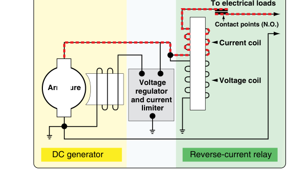
In a multi-source aircraft electrical system, two invisible dangers lurk whenever a generator is connected to a battery or another generator: current flowing the wrong direction, and unequal load sharing between sources. Reverse current cutout relays guard against the first problem by automatically disconnecting a generator whenever it falls below battery voltage, preventing the battery from discharging back through the generator armature. Paralleling circuits address the second problem by continuously trimming each generator's output so that every source shares the electrical load in proportion to its rating. Together, these two systems form the backbone of reliable DC power management on certificated aircraft, and they are heavily tested on the FAA Airframe Knowledge Exam.
Understanding how each circuit works — not just what it does — is the key to troubleshooting real faults and answering scenario-based exam questions correctly. This article walks through the electromechanical principles, the critical numbers, and the most common misconceptions.
The Reverse Current Problem
A DC shunt-wound generator produces output voltage that is directly related to field excitation and rotational speed. At idle or during shutdown, generator output voltage drops below the bus voltage maintained by the battery. Without protection, the battery would then push current backwards through the generator's armature windings, attempting to motor the generator. This reverse current accomplishes nothing useful — it drains the battery, can overheat the armature, and in severe cases can damage the commutator and brushes. The solution is a device that acts like an automatic, voltage-sensitive switch: the reverse current cutout relay, sometimes called the reverse current cutoff relay or simply the cutout.
How the Reverse Current Cutout Relay Works
The classic cutout relay contains two coils wound around a single iron core, plus a set of normally open contacts. The voltage coil (also called the shunt coil) is wound with many turns of fine wire and is connected in parallel with the generator output — it monitors generator voltage at all times. The current coil (series coil) is wound with a few turns of heavy wire and carries actual load current from the generator to the bus.
When the generator comes online and its output voltage rises to the closing voltage — a value set slightly above nominal system voltage and specified in the aircraft's maintenance manual rather than a single fixed figure — the voltage coil produces enough magnetomotive force to close the relay contacts. This connects the generator to the bus. Current then flows from the generator through the current coil toward the battery and loads, and the current coil's magnetic field aids the voltage coil field, holding the contacts firmly closed.
Now consider what happens when generator output falls below bus voltage — for instance, as the engine decelerates or the generator develops a fault. Current begins to reverse direction through the current coil. Because the current coil's field now opposes the voltage coil field, the net holding force on the relay's movable contact armature decreases. The spring tension on the contacts opens them, disconnecting the generator from the bus before the reverse current can reach a damaging level. The trip current — the reverse current magnitude at which the relay opens — is a carefully calibrated specification that is aircraft- and component-specific rather than a standardized value. This value is found in the aircraft's maintenance manual and should be verified during periodic testing.
Single-Unit Voltage Regulators with Integrated Cutout
On older light aircraft, the voltage regulator, current limiter, and reverse current cutout were three separate units mounted together in a regulator box. Modern aircraft often integrate all three functions into a solid-state voltage regulator, but the underlying logic is identical. Technicians working on classic Cessna, Piper, and Beechcraft aircraft will regularly encounter the electromechanical three-unit regulator assembly, and the FAA exam expects familiarity with both approaches.
Paralleling Circuits in Multi-Generator Systems
Larger aircraft — twins, turboprops, and early jet transports — commonly use two or more DC generators whose outputs are connected to a common bus. If two generators are simply wired to the same bus, small differences in their terminal voltages cause one generator to carry most of the load while the other barely contributes. Over time, this imbalance can overload one unit and underutilize another, reducing service life and creating a potential for overheating.
A paralleling circuit (also called an equalizing circuit or load-sharing circuit) continuously monitors the output current of each generator and adjusts their field excitation to equalize the load. The fundamental operating principle uses an equalizer bus — a dedicated conductor that interconnects a point in each generator's voltage regulator circuit.
How the Equalizer Bus Works
Each generator has a shunt resistor (or current transformer in more sophisticated systems) in its output lead that develops a small voltage proportional to load current. These sample voltages are fed to a common equalizer bus. If generator A is carrying more current than generator B, its sample voltage is higher. The difference in voltage on the equalizer bus causes a corrective signal that reduces generator A's field excitation (lowering its output voltage and thus its current) while simultaneously increasing generator B's field excitation. The process continues until the sample voltages — and therefore the output currents — are equal. This happens automatically and continuously, with correction times typically measured in fractions of a second.
A critical maintenance point: the equalizer bus is a low-voltage, low-current signal circuit. An open in the equalizer bus will cause the paralleling function to fail, and one generator may end up carrying the entire load while the other floats at minimum output. A short in the equalizer bus can cause a generator to lose voltage regulation entirely. Technicians must treat equalizer bus wiring with the same care as instrument signal wiring — any corrosion, chafing, or loose terminal can degrade parallel operation.
Why These Systems Matter for Safety
Reverse current protection is not a convenience feature — it is a fundamental safeguard against electrical fire and battery exhaustion. An unprotected reverse current path during engine shutdown can generate enough heat in the armature to melt insulation. On the other hand, a cutout relay that opens prematurely (too-low closing voltage or too-sensitive trip current) causes nuisance disconnects and leaves the electrical system running on battery alone without warning.
Paralleling failures are equally insidious. An aircraft with two generators where one carries 90% of the load and the other carries 10% will appear to have redundancy — until the overloaded generator fails. Proper load sharing ensures true redundancy: if one generator trips offline, the other has enough margin to carry essential loads. FAA regulations under 14 CFR §§ 23.1351 and 25.1351 address electrical system and equipment capacity and generator distribution requirements, and these requirements work together with the broader system safety analysis provisions of 14 CFR §§ 23.1309 and 25.1309, which require that the design account for failure conditions affecting essential services; proper paralleling circuit function supports demonstrating that compliance.
Key Numbers and Rules
- Closing voltage: The generator output voltage at which the cutout relay closes — typically set slightly above the nominal system voltage. There is no single FAA-standardized figure; the exact value is specified in the aircraft's maintenance manual.
- Reverse current trip value: The magnitude of reverse current at which the cutout opens; this value is aircraft- and component-specific and must be verified against the applicable maintenance manual during regulator box servicing, rather than assumed from a general range.
- Equalizer bus voltage: A low-level signal (often millivolts to a few volts) — handle wiring accordingly during inspection.
- Load imbalance tolerance: There is no universal FAA-mandated load-sharing tolerance; acceptable imbalance between paralleled generators is determined by the specific aircraft manufacturer's maintenance manual specifications.
- Regulatory basis: Electrical system protection requirements appear in 14 CFR §§ 23.1351, 25.1351, and related subparts including §§ 23.1309/25.1309; AMT certification standards reference FAA-H-8083-31 (Aviation Maintenance Technician Handbook — Airframe), Volume 2.
Common Test Traps
- Confusing voltage coil and current coil roles: The voltage coil closes the relay when generator voltage is sufficient. The current coil aids the voltage coil during normal forward current and opposes it during reverse current, triggering the trip. Many students reverse this logic.
- Assuming the cutout relay is just an on/off switch: It is a calibrated electromechanical device with specified closing and trip values. Replacing it with an uncalibrated relay or adjusting it improperly creates a hazard — always refer to the maintenance manual.
- Overlooking the equalizer bus during troubleshooting: When one generator in a parallel system carries all the load, students often blame the lightly-loaded generator's voltage regulator. The equalizer bus circuit is the first place to look.
- Thinking paralleling circuits are only for AC systems: While AC paralleling (synchronizing frequency and phase) is more complex, DC paralleling with equalizer buses is a distinct, well-established system used on many reciprocating-engine twins and older turboprops — both are tested.
- Misidentifying when the cutout opens on shutdown: The cutout does not open the instant the engine starts to shut down — it waits until reverse current reaches the trip threshold. Students sometimes think it opens the moment generator voltage drops below the closing voltage, but the series coil field must reverse before the relay opens.
Mastering these two circuits gives an AMT candidate a solid foundation not just for the written exam but for real shop work — the ability to read a generator regulator schematic, identify the three coils, and understand why a relay that closes too early or trips too late is as dangerous as one that never closes at all.