Every aircraft electrical system — from a simple landing light circuit to a complex avionics bus — is built on the same fundamental circuit configurations that students learn in basic electricity. The series circuit is the most straightforward of these configurations, yet it underlies some of the most critical troubleshooting concepts an Aviation Maintenance Technician (AMT) will ever use. Understanding exactly how voltage, current, and resistance relate to one another in a series circuit is not only essential for passing the FAA AMT General knowledge test, but is genuinely indispensable in the hangar.
A series circuit is defined as a circuit in which all components are connected end-to-end along a single path, so that there is only one route for current to travel from the negative terminal of the source, through the load or loads, and back to the positive terminal. Think of it like a one-lane road: every vehicle must pass every point along the route in the same sequence, and there are no alternate detours. This single-path characteristic is the key to every voltage, current, and resistance relationship discussed below.
How a Series Circuit Works
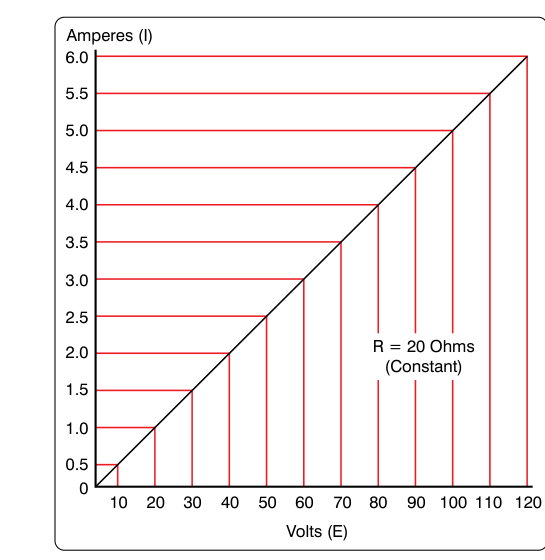
To understand series circuit behavior, you must start with Ohm's Law: E = I × R, where E is electromotive force (voltage) in volts, I is current in amperes, and R is resistance in ohms. In a series circuit, this relationship applies both to individual components and to the circuit as a whole. The three foundational rules of series circuits flow directly from this law and from the conservation of energy.
Rule 1: Current Is the Same Everywhere
Because there is only one path for electrons to travel, the same quantity of electrons that leaves the source must pass through every component in the circuit before returning to the source. This means the current (I) is identical at every point in a series circuit, regardless of how many resistors are present or what their individual values are. If you measure current with an ammeter at the beginning of the circuit, the middle, or the end, you will read the same value every time. This is a critical diagnostic principle: if you find different current readings at different points in what should be a series circuit, you have found a wiring fault or a parallel branch that should not be there.
Rule 2: Total Resistance Is the Sum of All Individual Resistances
Every component in a series circuit adds its resistance to the total. The formula is simply: Rtotal = R1 + R2 + R3 + ... + Rn. For example, if a circuit contains three resistors of 10 ohms, 20 ohms, and 30 ohms, the total resistance seen by the source is 60 ohms. Adding more loads in series always increases total resistance and therefore decreases total current, assuming source voltage remains constant. This is the opposite of what happens in a parallel circuit, and the distinction is frequently tested on FAA exams.
Rule 3: Voltage Divides Proportionally
The source voltage is shared among all components in a series circuit. The amount of voltage that drops across each individual component — called the voltage drop — is directly proportional to that component's resistance. Using Ohm's Law for each component: En = I × Rn. Because current (I) is the same for all components, a component with a higher resistance will have a larger voltage drop, and a component with a lower resistance will have a smaller voltage drop. The sum of all individual voltage drops must always equal the source voltage. This is a restatement of Kirchhoff's Voltage Law (KVL), which states that the algebraic sum of all voltages around any closed loop in a circuit equals zero.
Worked Example
Consider a 28-volt aircraft bus powering three resistors in series: R1 = 4 ohms, R2 = 8 ohms, and R3 = 16 ohms. Here is how you solve it step by step:
- Total resistance: Rtotal = 4 + 8 + 16 = 28 ohms
- Total current: I = E ÷ R = 28 V ÷ 28 Ω = 1 ampere (and this 1 ampere flows through every component)
- Voltage drop across R1: E1 = 1 A × 4 Ω = 4 volts
- Voltage drop across R2: E2 = 1 A × 8 Ω = 8 volts
- Voltage drop across R3: E3 = 1 A × 16 Ω = 16 volts
- Verification: 4 V + 8 V + 16 V = 28 V ✓ (equals source voltage)
This example illustrates how each resistor claims its proportional share of the available voltage. R3, which has four times the resistance of R1, also drops four times the voltage. The relationships are clean and predictable — which is exactly why Ohm's Law and KVL are so powerful as troubleshooting tools.
Why Series Circuit Behavior Matters in Aviation Maintenance
Aircraft electrical systems routinely include components wired in series for good reasons. Switches, fuses, and circuit breakers are always wired in series with the loads they protect, ensuring that opening any one of these devices breaks the only available current path and de-energizes the entire circuit. A burned-out fuse or a tripped circuit breaker creates what is effectively an open circuit — infinite resistance at that point — which forces the voltage drop for the entire source voltage to appear across the open, leaving zero voltage available to the load. This is why a technician measuring voltage across a blown fuse will read full source voltage across the fuse itself, while the downstream load reads zero. Understanding series circuit voltage distribution makes this instantly logical rather than mysterious.
An open circuit in a series circuit kills the entire circuit — all loads go dead — because the single current path is broken. This is different from a parallel circuit, where an open in one branch leaves other branches unaffected. The all-or-nothing nature of series circuit failure is both a troubleshooting clue and a safety feature: a fuse in series guarantees that an overcurrent condition removes power from the entire protected circuit simultaneously.
A short circuit in a series circuit — a path of near-zero resistance — bypasses one or more components. This lowers total resistance, increases total current, and shifts the voltage distribution so that nearly all the source voltage now drops across the remaining resistance rather than being shared. Short circuits in aircraft wiring can cause overheating, insulation damage, and fire, which is why proper wire sizing and overcurrent protection are regulatory requirements under 14 CFR Part 23 and Part 25 standards for aircraft certification.
Key Numbers and Rules
- Current rule: Itotal = I1 = I2 = I3 — current is identical at all points.
- Resistance rule: Rtotal = R1 + R2 + R3 — total resistance is the arithmetic sum.
- Voltage rule: Esource = E1 + E2 + E3 — source voltage equals the sum of all voltage drops.
- Ohm's Law applies at every level: to the whole circuit and to each individual component.
- Open circuit effect: all current stops; full source voltage appears across the open break; all loads read zero volts.
- Short circuit effect: total resistance decreases; current increases; voltage redistribution can overstress remaining components.
- Kirchhoff's Voltage Law (KVL): the algebraic sum of all voltages around a closed loop equals zero — the mathematical basis for the voltage drop rule.
Memory Aid
"Series Shares Voltage, Keeps Current Constant" — In a series circuit, voltage is shared (divided) among components, but current stays constant throughout. This two-part phrase captures both fundamental rules and helps prevent the most common confusion students have when first comparing series and parallel circuits. You can also remember it with the initials S-V-C: Series, Voltage divides, Current is constant.
Common Test Traps
- Confusing series and parallel current rules: In a series circuit, current is the same everywhere. In a parallel circuit, current divides. The FAA exam will present scenarios where you must identify which rule applies — always identify the circuit type before applying any formula.
- Adding resistances incorrectly: For series circuits, resistance values are simply added together. Students sometimes try to use the parallel reciprocal formula (1/Rtotal = 1/R1 + 1/R2...) on a series circuit. Make sure you identify the configuration first.
- Forgetting that a fuse or switch IS a series element: Exam questions sometimes describe a circuit with a fuse and ask what happens when it blows. The answer is always that all current stops and the full source voltage drops across the open fuse — not just partial voltage and not just partial current reduction.
- Assuming voltage drop is equal across all resistors: Voltage drops are proportional to resistance, not equal. Only identical resistors will share voltage equally. A common trap question gives resistors of different values and asks for the voltage across a specific one — you must calculate I first, then apply E = I × R for that resistor.
- Misidentifying an open vs. a short: An open removes all current from the circuit; a short increases current by lowering resistance. The exam may ask for symptoms (e.g., "what does the ammeter read?") and expect you to distinguish between these two failure modes correctly.