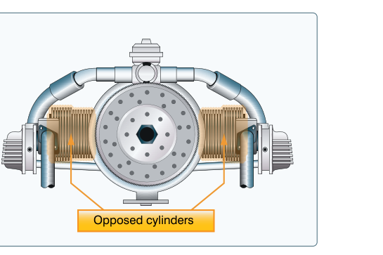
When a student walks into an aircraft maintenance hangar and peers under the cowling of a typical training airplane, they almost certainly encounter a horizontally opposed engine. This configuration dominates general aviation and light aircraft powerplants precisely because it solves several engineering challenges at once: it keeps the engine compact and low-profile, balances cylinder pairs across a common crankshaft, and delivers respectable power without excessive weight. For the FAA AMT Powerplant knowledge test, understanding not just what this engine looks like but how its design choices affect performance, maintenance access, cooling, and reliability is essential.
The horizontally opposed engine is sometimes called a flat engine or boxer engine because its cylinder pairs face each other horizontally and move in opposing directions along the crankshaft. Manufacturers such as Lycoming and Continental (now Continental Aerospace Technologies) have produced these engines in countless certified variants powering everything from two-seat trainers to high-performance singles and light twins. Mastering this configuration lays the groundwork for understanding nearly everything else in reciprocating engine theory.
Basic Layout and Component Arrangement
In a horizontally opposed engine, an even number of cylinders — typically four, six, or eight — are arranged in two banks positioned horizontally on opposite sides of the crankcase. Each bank contains half of the total cylinders. The cylinders project outward from the crankcase at approximately 180 degrees to each other, meaning the cylinder heads on the left bank face left and those on the right bank face right. This gives the engine its distinctively flat, wide silhouette.
The crankshaft runs longitudinally through the center of the crankcase and is connected to all pistons via connecting rods. Opposing pistons on each bank are typically arranged on a shared or closely paired crankpin (throw) so that the lateral forces generated by a piston moving outward on one bank are largely canceled by the opposing piston moving inward on the other bank; exact crank throw geometry varies by cylinder count and specific engine model. This inherent mechanical balance is one of the most important engineering advantages of the configuration.
The crankcase itself is typically cast from aluminum alloy in two halves that are bolted together along a horizontal plane. This split-case design simplifies internal assembly and disassembly during overhaul. The crankshaft, camshaft, and associated gear trains are housed inside the crankcase, which also serves as the primary structural backbone of the engine.
Cylinder Construction and Design
Each cylinder in a horizontally opposed engine is an individual, removable unit — a significant maintenance advantage over monobloc designs. A typical cylinder assembly consists of a steel barrel (the cylinder bore) that is either chrome-plated or nitrided for wear resistance, and is generally screwed and shrunk onto an aluminum alloy head, though technicians should always verify the specific attachment method against the applicable engine manual since details can vary by design. The aluminum head provides efficient heat dissipation through its fins while keeping overall weight low.
The exterior of both the barrel and head are covered with cooling fins that increase surface area for air cooling. In most certified horizontally opposed engines, cooling is accomplished entirely by ram air — air forced through baffles under the cowling by the aircraft's forward motion and, in many installations, the propeller slipstream. The baffles direct cooling air from an upper plenum (high-pressure area above the engine) down through the fins and out through lower cowl exits. Proper baffle condition is therefore a critical maintenance item; cracked or missing baffles cause uneven cylinder head temperatures (CHT) and can lead to premature engine wear or failure.
The piston inside each cylinder is also aluminum alloy and carries multiple rings: compression rings near the top to seal combustion gases, and oil control rings near the bottom to regulate oil film thickness on the cylinder wall. The piston is connected to the crankshaft by a forged steel connecting rod, typically of the H-beam cross-section design for strength-to-weight efficiency.
Valvetrain and Camshaft
Horizontally opposed aircraft engines use a single camshaft located in the lower portion of the crankcase. The camshaft is gear-driven from the crankshaft and rotates at one-half crankshaft speed, consistent with the four-stroke operating cycle. Each cam lobe actuates a hydraulic valve lifter (also called a tappet), which transmits motion through a pushrod to a rocker arm mounted on the cylinder head. The rocker arm pivots on a shaft and opens either the intake or exhaust valve as the pushrod rises.
Modern certified horizontally opposed engines almost universally use hydraulic lifters rather than solid lifters. Hydraulic lifters automatically compensate for thermal expansion of the valvetrain components, maintaining near-zero valve clearance across a range of operating temperatures. This eliminates the need for routine valve clearance (tappet gap) adjustment — a maintenance convenience compared to older solid-lifter designs — though proper oil pressure and viscosity are essential for their correct operation.
Ignition System
Aircraft horizontally opposed engines use a dual magneto ignition system. Two completely independent magnetos — each with its own set of ignition leads and spark plugs — fire two spark plugs per cylinder, one in the upper portion of the cylinder head and one in the lower. This dual-plug arrangement improves combustion efficiency by initiating the flame front from two points simultaneously, which produces more complete combustion, reduces detonation tendency, and provides redundancy. If one magneto system fails, the engine continues to run on the other, though with a noticeable drop in RPM detectable during the magneto check.
The magneto check performed during run-up verifies that each magneto is functioning correctly and that the RPM drop when switching to a single magneto does not exceed manufacturer limits. There is no single FAA-mandated universal limit; typical general guidance found in many POHs is around 150 RPM maximum drop on a single magneto, with no more than 50 RPM difference between the two magnetos, though technicians must always reference the specific engine's Type Certificate Data Sheet or Pilot's Operating Handbook for exact limits.
Lubrication System
Most horizontally opposed engines use a wet-sump lubrication system, in which oil is stored in a sump at the bottom of the crankcase. A gear-driven oil pump draws oil from the sump, pressurizes it, and distributes it through drilled passages in the crankcase and crankshaft to bearings, connecting rod journals, and other moving parts. An oil pressure relief valve maintains system pressure within design limits. Pressure-side filtration removes contaminants before oil reaches critical components.
Some higher-powered horizontally opposed engines use a dry-sump system, in which oil is stored in a separate external tank rather than in the engine sump. A scavenge pump returns oil from the crankcase to the tank while a pressure pump supplies oil to the engine. Dry-sump systems improve oil capacity, reduce the risk of oil starvation during unusual attitudes, and lower the engine's profile by eliminating a large bottom sump.
Why the Configuration Matters
The horizontally opposed layout provides several practical benefits that directly affect airworthiness and maintenance. The low profile keeps the engine's center of gravity close to the aircraft's longitudinal axis and places the cylinders low enough that pilots have reasonable forward visibility over the nose. The inherent cylinder-pair balance reduces vibration, decreasing fatigue stress on airframe attach points and engine mounts. Individual removable cylinders mean a single cylinder with worn bores or a cracked head can be replaced without removing or splitting the entire engine. And the accessible valvetrain — pushrods, rocker arms, and valve covers on the outside of each cylinder head — simplifies inspection and top overhaul procedures.
Key Numbers and Rules
- Camshaft speed: Rotates at one-half crankshaft speed in a four-stroke engine.
- Cylinder arrangement: Even numbers (4, 6, or 8) in two horizontally opposed banks.
- Cooling method: Air-cooled via ram-air and baffles in nearly all certified light aircraft horizontally opposed engines.
- Ignition: Dual magneto system with two spark plugs per cylinder for redundancy and efficiency.
- Lubrication: Wet-sump (most common) or dry-sump for higher-power or aerobatic variants.
- Cylinder material: Steel barrel with aluminum alloy head; fins machined integrally into both for air cooling.
- Firing order: Varies by manufacturer and number of cylinders; always reference the specific engine's overhaul manual or Type Certificate Data Sheet.
- TBO (Time Between Overhaul): Established by the engine manufacturer; not federally mandated for Part 91 operations but a critical maintenance planning figure.
Common Test Traps
- Camshaft speed confusion: The camshaft turns at one-half crankshaft speed — not the same speed. The four-stroke cycle requires each valve to open only once every two crankshaft revolutions.
- Magneto RPM drop limits: Students sometimes memorize a single number, but limits vary by engine model. The key concept is that the drop must be within the manufacturer's limits and that a zero drop can indicate a grounding problem (the magneto is not actually being switched off).
- Wet vs. dry sump confusion: Most light aircraft engines are wet-sump; dry-sump is the exception for higher-power or aerobatic variants. Know which stores oil in the crankcase (wet) vs. an external tank (dry).
- Hydraulic lifter maintenance: Because hydraulic lifters self-adjust, routine valve clearance setting is not required — but this does not mean the valvetrain is maintenance-free. Oil condition, lifter condition, and pushrod integrity still require inspection per the maintenance schedule.
- Baffle condition and CHT: Damaged baffles are a common cause of high cylinder head temperatures. Exam questions may link baffle failure to engine cooling problems; always connect baffle integrity to the ram-air cooling circuit.