Aircraft fluid systems — hydraulic lines, fuel lines, pneumatic lines, and oil lines — depend on tubing that carries pressurized fluid without leaking, cracking, or collapsing. Every time a technician fabricates or replaces a section of metal tubing, the quality of each bend determines whether that line will survive thousands of pressure cycles in service or fail at the worst possible moment. Understanding tube bending techniques and the concept of minimum bend radius is therefore one of the most practically important skills in the AMT General curriculum and a topic the FAA knowledge test examines closely.
This article covers the mechanics of tube bending, why a minimum bend radius exists, how to use the tools correctly, what acceptable and unacceptable bends look like, and the specific rules and numbers you need to know for the test and the shop floor.
Why Tube Bending Is Challenging
When you bend a straight tube, the material on the outside of the curve is stretched in tension while the material on the inside is compressed. If the bend is too tight — meaning the radius is too small — the outer wall thins dangerously and the inner wall wrinkles or collapses inward. Either condition weakens the tube structurally and disrupts smooth fluid flow. A collapsed or wrinkled inner wall also creates turbulence that accelerates erosion of the tube wall from the inside, a hidden hazard that may not be visible during inspection.
The challenge is compounded by the variety of tubing materials used in aircraft — 1100 and 3003 aluminum alloys for low-pressure applications, 5052-O aluminum for higher pressures, and corrosion-resistant steel (CRES) or titanium for hydraulic systems operating at very high pressures. Each material has different ductility and therefore a different ability to tolerate bending without damage.
Minimum Bend Radius: What It Is and How It Is Determined
The minimum bend radius is the smallest allowable radius measured to the centerline of the tube through a bend. Bending to a radius smaller than the minimum for a given tube outside diameter (OD) and wall thickness risks thinning, wrinkling, or flattening the tube to an unacceptable degree.
The FAA specifies minimum bend radii in terms of the tube's outside diameter. As a general rule, the minimum bend radius is approximately three times the outside diameter of the tube for most aluminum alloy tubing commonly used in aircraft systems. For harder or thicker-walled materials, the minimum radius is larger. These values are published in the manufacturer's maintenance manuals and in FAA Advisory Circular 43.13-1B (Acceptable Methods, Techniques, and Practices — Aircraft Inspection and Repair), which serves as the authoritative practical reference for AMTs.
For example, a tube with a 1/2-inch outside diameter should not be bent to a centerline radius of less than approximately 1-1/2 inches (3 × 0.5 in). A 3/4-inch OD tube requires a centerline radius of at least approximately 2-1/4 inches. Always verify exact values against the applicable manufacturer data or AC 43.13-1B for the specific material and wall thickness in question, because some applications call for a larger multiplier.
Tube Bending Tools
Hand Tube Benders
The most common tool for smaller-diameter tubing (typically up to about 1/2 inch OD) is the hand tube bender, sometimes called a hand-operated bending tool. It consists of a formed radius block (the bend die), a clip or clamp that holds the tube against the die, and a follower block or shoe that keeps the outer wall from flattening as the bend is made. The radius block is machined to a specific radius for a specific tube OD, so the correct block must be selected for the job. Graduations on the tool allow the technician to measure the angle of bend directly.
To use a hand bender correctly, place the tube in the bender so the starting mark aligns with the zero-degree reference on the radius block. Apply smooth, steady pressure through the handle — never jerk or force the bend, which can cause the tube to slip or kink. Bend slightly past the desired angle to account for springback, then verify the final angle with a protractor or the degree markings on the tool.
Mechanical and Production Benders
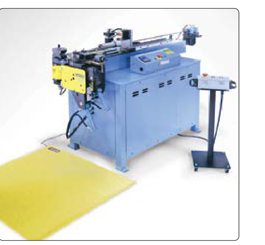
For larger tubing or production quantities, mechanically assisted benders (gear-driven or hydraulic) apply the same principle but with greater leverage and precision. These tools are essential for steel and titanium tubing, which resist bending far more than aluminum. Mandrel benders insert a support inside the tube during the bend to prevent wall collapse and are required for thin-walled tubing or tubing that must meet tight roundness tolerances after bending.
Performing the Bend: Step-by-Step Best Practices
- Select the correct bender for the tubing OD and material. Using a bender designed for a different size will not support the tube wall properly and may cause damage.
- Measure and mark the tube carefully before bending. Identify where the bend must begin and plan for any additional bends downstream, keeping in mind that material is consumed in each curve.
- Anneal if necessary. Some hard aluminum alloys or stainless steel may be annealed (softened by controlled heating and cooling) before bending to reduce the risk of cracking. Consult the applicable data; not all alloys benefit from or permit annealing.
- Make the bend smoothly with steady, continuous pressure. Pausing mid-bend or applying jerky force can create flat spots.
- Account for springback. Metal tubing springs back slightly after the bending force is released. Bend a few degrees past the target angle, then measure and adjust.
- Inspect immediately after bending for any signs of kinking, wrinkling, flattening, or surface cracking.
Inspecting Bends for Acceptability
FAA guidance in AC 43.13-1B establishes the criteria for acceptable bends. A bend is acceptable when the tube remains round (or very nearly so), the wall shows no cracks, and the inner radius shows no sharp kinks or corrugations. A small amount of smooth ovality is permitted; the tube's outside diameter at the bend must not be reduced by more than approximately 25 percent of the original diameter — in other words, the flattening must not reduce the minor axis to less than 75 percent of the original OD. Wrinkles on the inside of the bend are not acceptable, even if they appear minor, because they concentrate stress and will crack in service.
Cracks visible on the outer surface of the bend are cause for immediate rejection. The tubing must be cut out and replaced with a new section; cracked tubing cannot be repaired by straightening or rewelding in most aircraft applications.
Key Numbers and Rules
- Minimum bend radius (general rule): approximately 3 times the tube OD, measured to the centerline — always verify against AC 43.13-1B or the manufacturer's data for the specific material.
- Maximum allowable flattening: the tube OD at the bend must not decrease to less than 75 percent of the original OD.
- No wrinkles permitted on the inside radius of any completed bend in aircraft tubing.
- No cracks permitted anywhere on the tube after bending — cracked tubing must be replaced.
- Hard aluminum alloys (such as 2024-T3) are generally not bent in the heat-treated condition; 5052-O and 1100 are preferred for bending applications.
- Mandrel bending is required when thin-walled tubing must maintain acceptable roundness through the bend.
- Springback compensation: always overbend slightly and measure; the exact springback depends on the material and wall thickness.
Common Test Traps
- Confusing OD with centerline radius. The minimum bend radius is measured to the centerline of the tube, not the outer or inner surface. A tube with a 1/2-inch OD bent to a 1-1/2-inch centerline radius meets the 3× rule, but if you measure to the inside of the bend the number looks smaller — know what you are measuring.
- Assuming wrinkles on the inside of a bend are acceptable. The test may suggest that slight inner-radius wrinkles are a minor cosmetic issue. They are not — they are cause for rejection because of stress concentration and future cracking.
- Selecting the wrong size bender block. Using a bender die meant for a larger tube OD on a smaller tube will not control the outer wall, and the tube may flatten or kink even if the angle and radius look correct.
- Forgetting to account for springback. A student who bends exactly to the target angle and removes the tube may find the angle is a few degrees short. Always plan to overbend slightly.
- Thinking all aluminum alloys can be bent equally. Heat-treated alloys like 2024-T3 are far more crack-prone during bending than annealed alloys like 5052-O. The test may present scenarios where the wrong alloy choice leads to a cracked bend.
Practical Summary
Proper tube bending in aircraft maintenance is not a casual skill — it requires the right tool, the correct minimum bend radius for the tube size and material, smooth and steady technique, and a disciplined post-bend inspection. Every bend that leaves the shop and enters the aircraft will be subjected to vibration, pressure cycles, and temperature swings throughout the aircraft's service life. A bend made correctly the first time protects the aircraft and everyone aboard; a bend made carelessly or with the wrong tool can initiate a crack that leads to a fluid leak or system failure. Master these fundamentals, and you will carry a skill that directly supports airworthiness every day of your career.