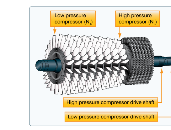
Most modern transport-category turbofan engines are built around a dual-spool architecture — two completely independent rotating assemblies sharing the same engine casing yet turning at entirely different speeds. Understanding why engineers chose this arrangement, how each spool behaves across the full power spectrum, and what abnormal spool relationships reveal about engine health is knowledge that belongs in every ATP candidate's mental toolkit. The dual-spool concept touches engine starting, thrust management, high-altitude operations, in-flight relights, and the cascade failures that can follow a single spool anomaly.
What the Two Spools Actually Are
The N1 spool — also called the low-pressure (LP) spool — links the large fan at the engine inlet, any low-pressure compressor (LPC) booster stages immediately behind the fan, and the low-pressure turbine (LPT) stages at the rear of the core. These components are all bolted to a common inner shaft. The N2 spool — the high-pressure (HP) spool — connects the high-pressure compressor (HPC) to the high-pressure turbine (HPT) through a concentric outer shaft that physically surrounds the N1 shaft. Because the two shafts are mechanically independent and separated by bearings, each spool is free to rotate at whatever speed the aerodynamic and thermodynamic forces on its own blades dictate.
This independence is the entire point of the dual-spool design. A single-spool engine must compromise: one shaft speed cannot simultaneously be optimum for the large, slow-turning fan and the small, fast-spinning core compressor. By splitting the system, engineers allow the HPC to run at the high RPM needed for pressure ratio efficiency while the fan runs at a much lower RPM consistent with acceptable blade-tip Mach numbers and noise levels. The result is higher overall pressure ratios, better fuel efficiency, and broader stable operating ranges — exactly what high-bypass transport engines demand.
How Each Spool Is Measured and Displayed
Both N1 and N2 are displayed as a percentage of a design-reference RPM, never as raw shaft RPM. The actual RPM corresponding to 100% N1 or 100% N2 varies significantly from one engine model to the next and is defined in that engine's Airplane Flight Manual (AFM). Because the percentage scale is normalized, 100% on one engine model tells a pilot nothing about the shaft speed on a different model; the only meaningful comparison is against that engine's own limits.
On the vast majority of modern turbofan transports, N1 is the primary thrust-setting parameter. Autothrottle computers command N1 targets for every thrust rating — takeoff (TO), go-around, maximum continuous (MCT), climb (CLB), and cruise (CRZ) — because N1 most directly reflects the fan's mass airflow and, consequently, the net thrust produced. N2 is displayed as a secondary cross-check and is monitored closely during starting. Some older designs and certain engine models use Engine Pressure Ratio (EPR) rather than N1 as the primary thrust indicator; ATP candidates should know which parameter applies to their specific type-rating aircraft, since the knowledge test may probe the distinction.
Engine Starting: Why N2 Leads and N1 Follows
The start sequence is one of the most tested topics related to spool dynamics. When a pilot initiates an engine start, the starter — typically a pneumatic air-turbine starter fed by APU bleed air or a ground cart — engages the N2 spool only. The starter spins the HPC to a speed sufficient to generate airflow through the combustion chamber before the fuel control unit introduces fuel and the ignitors fire; the exact N2 percentage at which fuel is introduced is engine-type specific and defined by the manufacturer. Once light-off occurs and combustion is self-sustaining, the HPT drives N2 upward without starter assistance, and the starter cuts out at a manufacturer-specified N2 percentage.
As expanding combustion gases flow through the LPT stages, N1 begins to rise — driven by the same gas stream now exiting the HPT. Pilots confirm that N1 responds within an expected time window after light-off; a sluggish or absent N1 rise can indicate a hung start or LPT anomaly. N1 settling at ground idle typically lags N2 idle stabilization by several seconds, which is normal. The important takeaway: N2 always rises first; N1 always follows. Any test question implying the opposite describes an abnormal sequence.
Acceleration Response and Throttle Dynamics
Because the N2 spool is smaller and has lower rotational inertia than the large N1 fan assembly, N2 responds faster to throttle advances. When a crew pushes the thrust levers forward briskly — as during a go-around or a rejected-takeoff abort reversal — N2 climbs sharply and almost immediately, while N1 lags by a noticeable interval. This lag is aerodynamic and mechanical, not a malfunction. Mistaking a normal N1 lag for engine trouble during a critical maneuver is a known human-factors pitfall; understanding the physics prevents that error.
During deceleration, the relationship reverses: the large fan's inertia keeps N1 spinning longer after a throttle reduction, while N2 decays more quickly. In an engine failure scenario at altitude, both spools will windmill from ram airflow; the relative windmill percentages of N1 versus N2 are engine-type specific and depend on the individual design's aerodynamic characteristics, so pilots should reference their specific type's published windmill data rather than assume a universal relationship.
High-Altitude Spool Considerations
At cruise altitudes, ambient air density is a fraction of sea-level density, and the relationship between altitude, air density, and the N1/N2 percentages required for a given thrust setting is complex and specific to each engine design. The AFM defines separate N1 and N2 maximum limits that must never be exceeded regardless of altitude. Operators flying near the certified ceiling must be attentive to any trend toward limit exceedance, particularly during step climbs or when ambient temperature is warmer than standard.
Engine Health Monitoring and Abnormal Spool Relationships
Every engine has a well-characterized N1-to-N2 relationship at each power setting and altitude. Engine health trending programs compare recorded N1, N2, exhaust gas temperature (EGT), fuel flow, and oil parameters against baseline values. Deviations from the expected N1/N2 ratio can point to specific faults:
- Abnormally high N2 for a given N1: May indicate an N1 shaft problem, LPT blade deterioration reducing energy extraction from the gas stream, or a significant bleed-air leak reducing effective core loading.
- Abnormally low N2 for a given N1: Can suggest HPC fouling, compressor stall, or a deteriorating HPT reducing the spool's self-sustaining capability.
- High EGT with normal N1/N2: Often points to combustor hot spots, turbine blade cooling passage blockage, or an over-rich fuel schedule — not a spool speed issue per se, but requiring trend correlation.
Because most accessory gearboxes are driven off the N2 spool — including hydraulic pumps and integrated drive generators — an N2 mechanical failure can cascade into simultaneous hydraulic and electrical system abnormalities. This coupling is why dual-spool independence does not mean dual-spool isolation from the rest of the aircraft systems.
In-Flight Relight Envelope
After a flameout, successful airstart depends on having enough N2 windmill speed to pressurize the combustion chamber adequately for fuel atomization and ignition. Manufacturers publish in-flight relight envelopes — combinations of airspeed and altitude — in the Quick Reference Handbook (QRH) that ensure sufficient windmill N2 for a successful relight. Flying below the minimum relight airspeed, particularly at high altitude where air density is low, may produce inadequate N2 windmill to sustain combustion after fuel introduction, resulting in a hung or failed relight. Both N1 and N2 should be noted before and during the relight attempt to evaluate whether conditions fall within the envelope.
Key Numbers and Rules
- N1 and N2 are percentage values referenced to each engine model's design RPM — never raw shaft RPM.
- N1 is the primary thrust indicator on most modern high-bypass turbofans; some older designs use EPR.
- Starter engages N2 only; N1 rises after combustion drives the LPT.
- N2 responds faster to throttle inputs due to lower rotational inertia.
- Both spool redline limits are AFM-defined and must not be exceeded at any altitude.
- Accessories (hydraulics, electrics) are driven from the N2 gearbox — N2 anomalies can cascade system-wide.
- Relight success depends on adequate N2 windmill speed within the published envelope.
Common Test Traps
- N1 vs. EPR as primary thrust indicator: Most turbofan transports use N1; do not assume EPR unless the aircraft type specifies it. Know your type.
- Start sequence order: N2 rises first — always. A question suggesting N1 leads N2 during start describes an abnormality, not a normal sequence.
- Percentage ≠ absolute RPM: 100% N1 means different actual shaft speeds on different engine models. Never cross-compare raw percentages across types.
- Independent spools, but shared accessories: Students often think spool independence means full system isolation. It does not — the N2 gearbox powers critical aircraft systems.
- N1 lag during go-around: A slow N1 response immediately after a rapid thrust advance is aerodynamically normal, not a malfunction indicator, as long as N2 has risen smartly and EGT is within limits.
Memory Aid
Use "Core First, Fan Follows" — the high-pressure core (N2) starts, accelerates, and responds first in every scenario; the fan (N1) is what you ultimately use to set thrust. Picture igniting a blowtorch (N2 core) before the heat spins a large pinwheel downstream (N1 fan): fire first, pinwheel follows.