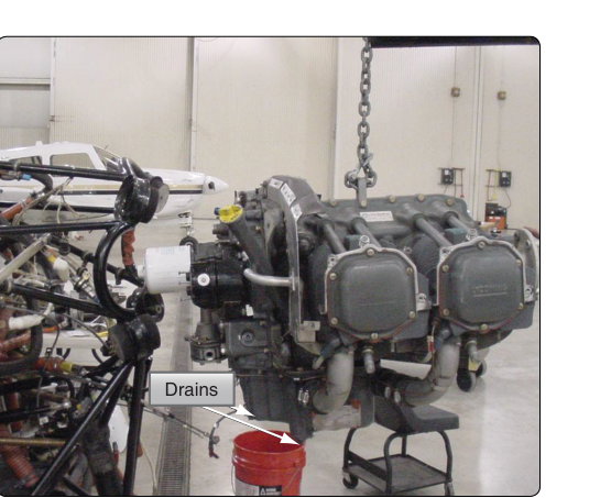
Before an aircraft engine can be safely removed from the airframe, all fluids must be drained and every fluid line must be disconnected in a controlled, deliberate sequence. The oil system receives special attention because engine oil circulates under pressure through numerous internal passages, external lines, coolers, and accessories — and residual oil can create slip hazards, fire risks, and contamination problems if not managed properly. For the AMT preparing for the FAA Powerplant knowledge test, understanding why each step is performed is just as important as memorizing what to do. This article walks through the full procedure, covering the physics of drainage, line handling best practices, and the regulatory framework that governs the work.
Oil system work during engine removal is governed primarily by the aircraft manufacturer's maintenance manual and 14 CFR Part 43. The FAA's Aviation Maintenance Handbook (FAA-H-8083-32, Powerplant) addresses lubrication system principles, while Part 43 Appendix A defines major alterations, major repairs, and preventive maintenance. Always confirm the applicable maintenance manual is the authoritative source for torque values, line sizes, and sequence specifics on any given aircraft.
Understanding the Oil System Before You Drain It
A typical aircraft reciprocating engine uses a wet-sump or dry-sump lubrication system. In a wet-sump system, oil is stored in a sump integral to the engine crankcase, and gravity naturally pools it at the lowest point. In a dry-sump system — common on higher-performance and turbine engines — oil is stored in a remote tank, scavenged from the engine by dedicated scavenge pumps, and routed through an oil cooler before returning to the tank. Understanding which system you are working on determines where you drain, in what sequence, and how much residual oil you should expect to find in passages even after the main drain is opened.
Oil also circulates through external lines that connect the engine to the oil cooler, oil filter or filter adapter, external breather tubes, and sometimes to propeller governor oil passages. Each of these lines retains oil after the engine is shut down, so draining the sump alone does not fully evacuate the system. This fact is critical: residual oil in lines will spill when disconnected, and planning for that containment is not optional — it is part of the procedure.
Pre-Drain Safety Preparations
Before opening any drain, position the aircraft on level ground or on jacks so that oil flows toward the drain point as designed. Gather all required materials: an approved drain container of adequate capacity (typically more than the engine's full oil capacity to account for splashing and residual quantities), absorbent shop rags, appropriate personal protective equipment (PPE) including nitrile gloves and eye protection, and line-capping supplies such as clean plugs, caps, or plastic wrap secured with safety wire or tape. Prepare labels or tags for each line so that reconnection is unambiguous.
Confirm that the engine has been shut down long enough for oil to cool to a safe handling temperature, yet not so long that viscosity makes drainage unacceptably slow. Many shops prefer to drain oil while it is still warm, since warm oil flows more freely and carries more suspended contaminants out with it, giving a cleaner system; the manufacturer's maintenance manual is the authoritative source for any specific timing guidance, as FAA-H-8083-32 does not specify a numeric time window. Never open drain plugs on an engine that has just been shut down from high-power operation; hot oil and pressurized residual vapor can cause serious burns.
Draining the Oil: Step-by-Step Procedure
Position your drain container directly below the engine sump drain fitting. On most horizontally-opposed reciprocating engines, the sump drain is a threaded plug or quick-drain valve located at the lowest point of the crankcase. Using the correct tool (commonly a box-end wrench or an approved quick-drain key), slowly break the plug loose to allow air to enter the system gradually, preventing a sudden surge. Once the plug is fully removed, allow the oil to drain completely — actual drain time and oil quantity vary by engine model and are specified in the manufacturer's maintenance manual and type certificate data, not by a fixed FAA figure.
For dry-sump systems, also open the oil tank drain at its lowest fitting. Some oil tanks have both a main drain and a sediment trap or finger-screen drain at the very bottom; both should be opened and the sediment screen inspected and cleaned before reinstallation.
After the bulk of the oil has drained, inspect the drained oil. Note its color, clarity, and any particulate matter. Metal particles, carbon deposits, or milky discoloration (indicating water or coolant contamination) should be documented and investigated before reinstallation of the engine. The drain plug itself, if equipped with a magnetic insert, should be examined for ferrous metal particles as a condition indicator. This is a valuable maintenance diagnostic step that the FAA knowledge test may reference in the context of oil analysis and engine health monitoring.
Disconnecting Oil Lines: Sequence and Technique
Once the sump is empty, begin disconnecting external oil lines. The general principle is to work from the highest point in the system downward, so that any oil remaining in elevated lines drains into already-emptied lower sections rather than flooding a confined space unexpectedly. In practice, the maintenance manual will specify the exact sequence — always follow it.
For each line disconnection, use two wrenches when working on fittings: a backup wrench on the fitting body or adapter to prevent rotation, and a second wrench on the flare nut or B-nut. Failing to use a backup wrench is one of the most common causes of damaged fittings, twisted lines, and cracked tubing — all of which become expensive defects discovered during reinstallation. Apply steady, controlled force and never use impact tools on aluminum AN or MS line fittings.
As each line is disconnected, immediately cap or plug both the line end and the port on the engine or accessory. Use caps and plugs of the correct size — typically AN caps and plugs that match the thread or flare standard of the fitting. Improvised plugs made from rags or tape inserted into ports are unacceptable because they can fall into oil passages or introduce foreign object debris (FOD). Even brief, uncapped exposure allows moisture, dirt, and dust to contaminate precision internal surfaces.
Label each capped line with a durable tag indicating its origin port and destination. Color-coded tape or commercially available tag systems both work well. This step pays dividends during reinstallation and is a professionalism marker that inspectors look for. Some shops photograph the engine bay before disconnection as additional documentation.
Handling the Oil Cooler and External Accessories
The oil cooler retains significant oil volume even after the sump is drained. When disconnecting cooler lines, expect oil spillage and position your containment accordingly. If the cooler is being removed with the engine, leave it attached until all lines are capped; if it stays with the airframe, disconnect and cap its ports carefully. Inspect cooler inlet and outlet lines for condition — cracks, chafing, and deteriorated hose sections are commonly found during engine change work and should be replaced rather than reinstalled.
Propeller governor oil lines, if present, must also be disconnected and capped. These lines carry engine oil at regulated pressure to the governor, so they are part of the oil system even though they serve propeller pitch control. The governor itself may be removed with the engine or left on the engine pad depending on the removal plan; either way, the oil supply line to the governor must be capped at both ends.
Waste Oil Disposal
Used aircraft engine oil is a regulated waste product. It must be collected in approved containers and disposed of through a licensed recycler or waste oil collection service. Pouring used oil onto the ground, into drains, or into trash is illegal under EPA regulations and inconsistent with the professional and safety standards expected of certificated mechanics. Document the oil quantity drained; this information is useful for confirming that the system was fully evacuated and for tracking oil consumption trends if this is a routine oil change during an engine change rather than a first-run removal.
Key Numbers and Rules
- Two-wrench rule: Always use a backup wrench on any fitting body when tightening or loosening flare nuts or B-nuts to prevent line twisting and fitting damage.
- Drain container capacity: Use a container rated for more than the full system oil capacity — never guess that less will suffice.
- Cap and plug immediately: Every disconnected port — line end and engine/accessory port — must be capped before moving to the next disconnection.
- 14 CFR Part 43: All maintenance must be performed per approved data (manufacturer's maintenance manual) and entries made in the appropriate maintenance record, signed by the appropriately certificated individual.
- Magnetic drain plug inspection: Always examine magnetic drain plugs for metal particle accumulation and document findings before reinstallation.
- Warm oil drainage: Draining oil while warm generally improves flow and contaminant removal, but never open a drain immediately after high-power operation; consult the manufacturer's maintenance manual for any specific timing guidance rather than relying on a fixed interval.
Common Test Traps
- Assuming the sump drain evacuates the entire system: A common knowledge-test distractor. External lines, the oil cooler, and remote oil tanks all retain residual oil that will spill if not anticipated.
- Single-wrench on B-nuts: The test may ask the correct technique for disconnecting flared-tube fittings. The answer is always two wrenches — one as a backup to prevent fitting rotation.
- Improvised caps and plugs: Rags or tape in oil ports is never correct. The test expects AN-standard caps and plugs to prevent FOD and contamination.
- Oil temperature before draining: Some students confuse draining immediately after shutdown (burn risk) with the correct warm-but-cooled window; know that a brief cool-down period is appropriate, though the FAA handbook does not specify an exact number of minutes.
- Record-keeping: Part 43 requires a maintenance record entry for any oil system work. Omitting documentation is a regulatory violation regardless of how well the mechanical work was performed.