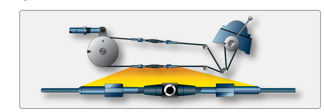
When an aircraft powerplant is removed for overhaul, replacement, or major repair, every control cable that connects the cockpit to the engine must be disconnected and then precisely re-rigged upon reinstallation. Engine control cables govern throttle position, mixture ratio, propeller governor speed, carburetor heat, and — on some aircraft — cowl flaps. A cable that binds, travels too little, or sits at an incorrect neutral position can deprive the pilot of full control authority at a critical moment. For the Aviation Maintenance Technician (AMT) working toward a Powerplant certificate, understanding the theory and hands-on procedure of control cable rigging is both an FAA knowledge test staple and a daily shop reality.
This article walks through the complete process: from identifying cable types and hardware, through rigging sequence and travel measurement, to the final operational checks required before returning an aircraft to service.
Types of Engine Control Cables
Most general aviation engine control cables are flexible push-pull or tension cables housed inside a conduit or routed through the airframe via fairleads and guides. The FAA's Aviation Maintenance Handbook (FAA-H-8083-32) describes two fundamental constructions used in powerplant applications:
- Flexible cable (7×7 and 7×19 construction): Seven strands of seven or nineteen individual wires each. The 7×19 cable is more flexible than 7×7 construction and is generally preferred wherever the cable must travel around pulleys or through tight bend radii; the choice between constructions depends on the specific bend requirements and manufacturer specification for that run, not simply proximity to the firewall. Throttle and mixture cables on most piston-engine aircraft use flexible cable.
- Push-pull control rods: Rigid or semi-rigid tubes with threaded rod-end bearings at each end. These are common on fuel injection systems and on connections between the throttle body and the induction manifold where precise, non-stretching linkage is required.
Regardless of type, the hardware at each cable end — rod-end bearings, clevis pins, turnbuckles, swaged terminals, or Nicropress sleeves — must be inspected for corrosion, wear, and security before any rigging work begins. A damaged terminal that passes a visual check may still fail a pull-force test; the AMT must apply the manufacturer's specified proof load where required by the aircraft maintenance manual (AMM).
Preparation Before Rigging
Rigging cannot begin until the engine is fully installed, all engine mounts are torqued to specification, and the engine is sitting in its final, level position on the airframe. Control cable geometry changes when the engine shifts even a small fraction of an inch; rigging before final mounting is a common and costly mistake.
Gather the following before starting:
- The Type Certificate Data Sheet (TCDS) and the specific AMM for the aircraft/engine combination — these contain the required cable travel in inches or degrees, rigging loads, and any special tooling callouts.
- A calibrated tensiometer appropriate for the cable diameter in use. Cable tension is measured in pounds and varies with temperature; most manuals provide a tension-versus-temperature chart.
- Rigging pins or fixtures called out in the AMM. Many manufacturers supply dedicated alignment fixtures that hold the cockpit controls at a defined reference position during rigging.
- A push-pull gauge for verifying control friction and breakout force where specified.
The Rigging Sequence
A logical sequence prevents having to undo completed work. Follow this general order, always cross-referencing the specific AMM:
- Route and secure the cable. Thread the cable through all fairleads, grommets, and firewall fittings. Ensure firewall pass-through grommets are intact and properly sealed — unprotected holes violate firewall construction and sealing requirements such as those found in 14 CFR 23.1191 and 23.1194 (or the corresponding provisions for the aircraft's certification basis).
- Set the cockpit control to the rigging reference position. For a throttle, this is typically full-closed (idle) or full-open (takeoff power), as specified. Insert any manufacturer rigging pins to hold this position.
- Set the engine-side component to its corresponding reference position. The throttle butterfly or fuel-injection servo arm must be positioned exactly at its stop — idle stop for idle rig, wide-open stop for maximum travel rig — before any cable tension is applied.
- Connect and adjust the cable end fitting. Thread the rod-end or clevis until the pin slides freely through both fittings without forcing. If a turnbuckle is used, thread it evenly from both ends to maintain equal thread engagement. The AMM will specify minimum thread engagement — typically no more than one thread showing outside the barrel, and no fewer than a defined minimum number of threads remaining inside.
- Set cable tension. Apply the specified tension using the tensiometer at a location free of bends and away from cable ends. Rigging tensions vary considerably by cable diameter, run length, and airframe manufacturer specification, so always use the AMM's temperature-corrected tension chart for the exact figure rather than a rule-of-thumb range. Over-tensioning causes premature wear and can deform fairleads; under-tension allows slack that produces slop and delayed throttle response.
- Safety the turnbuckle or jam nut. Turnbuckles are safety-wired using the single-wrap or double-wrap wire method (or an approved clip locking device) per AC 43.13-1B, with the double-wrap method generally preferred for larger-diameter cables. Jam nuts on rod-end bearings are torqued and, where required, secured with cotter pins through the clevis pin.
Verifying Full and Correct Travel
After initial rigging, remove any rigging pins and sweep the cockpit control through its full range — slowly and deliberately. Observe the engine-side component and verify:
- Full travel is achieved in both directions. The throttle plate must reach the idle stop and the wide-open stop simultaneously as the cockpit lever reaches its detents. If the engine component hits its stop before the cockpit lever does, the cable is too short or the adjustment is incorrect; if the cockpit lever bottoms out before the engine component reaches its stop, the cable is too long. Both conditions are unsafe.
- No binding occurs anywhere in the travel arc. Pull the throttle from idle to full power with a spring scale; friction must not exceed the AMM limit (often specified in pounds). Excessive friction indicates a kinked cable, a misaligned fairlead, or a failing conduit end fitting.
- Return to idle (or neutral) is positive and complete. Release the cockpit control and confirm the engine-side return spring pulls the component fully back to the idle stop. Engine control cables must never rely solely on cable push to return to idle — a separate return spring is required so that a broken cable causes the engine to revert to idle rather than stick at high power.
Mixture and Propeller Governor Cables
The mixture control cable connects the cockpit mixture lever to the fuel metering device — either the carburetor mixture needle or the fuel-injection servo lean/rich arm. Full-rich must place the metering device in its fully open (rich) position; full-lean (or idle cutoff) must completely shut off fuel flow when the pilot selects that detent. A rigging error here that leaves even a small gap at cutoff means the engine will not shut down on mixture — an obvious and dangerous discrepancy that must be caught during the operational check.
Propeller governor control cables on constant-speed installations connect the cockpit prop lever to the governor speeder spring. The AMM will specify the exact arm position at low RPM and high RPM detents. Over-travel of the governor arm beyond its designed arc can damage the governor internals, while under-travel prevents the propeller from reaching maximum RPM — reducing takeoff performance and potentially causing prop overspeed if the governor loses authority at one extreme.
Operational Test and Return to Service
With all cables rigged and safety-wired, conduct the full engine run-up per the AMM before signing the maintenance record. During the run-up, verify smooth and proportional throttle response, correct RPM range with the prop governor, positive mixture cutoff at shutdown, and — where applicable — proper carburetor heat valve actuation confirmed by the expected RPM drop. Any stiffness, lag, or failure to reach specified RPM limits requires the engine to be shut down and the rigging rechecked before flight.
The AMT must make a maintenance record entry under 14 CFR §43.9 describing the work performed, the date, the aircraft registration, and the AMT's certificate number and signature. The entry should reference the AMM revision and revision date used as the data source.
Key Numbers and Rules
- Thread engagement in a turnbuckle barrel: a minimum number of threads must remain inside as specified by the AMM; AC 43.13-1B's general guidance is commonly cited as no more than three threads visible outside the barrel, though this can vary with cable/turnbuckle size, so the AMM governs.
- Cable tensions are temperature-dependent and vary by cable diameter and run length; always use the AMM tension-temperature chart for the specific cable rather than a generic pound range.
- Full travel check: engine-side stops and cockpit-side stops must be reached simultaneously.
- Firewall grommets and pass-throughs must be sealed to maintain firewall integrity per 14 CFR 23.1191/23.1194 (or the applicable certification basis).
- Return to idle must be spring-positive — no relying on cable push alone for idle return.
- Maintenance record entry required under 14 CFR §43.9 before return to service.
Common Test Traps
- Rigging before final engine mount torque: The FAA knowledge test may describe a scenario where cables are rigged with the engine not fully secured. Recognize that engine position must be final before rigging begins.
- Ignoring the temperature correction on tensiometer readings: A cable tensioned correctly on a cold morning will read differently on a hot afternoon. Failure to use the temperature chart leads to over- or under-tension.
- Confusing simultaneous stops with sequential stops: A correct rig achieves cockpit and engine stops at the same moment. If one reaches its limit before the other, the rig is wrong regardless of which end gets there first.
- Overlooking the mixture cutoff check: Students often focus only on the throttle cable and forget that mixture cutoff must be verified to completely shut off fuel flow — not just reduce it.
- Assuming any thread showing on a turnbuckle barrel is acceptable: AC 43.13-1B's general guidance sets a typical maximum threads visible, but always defer to the aircraft-specific AMM as it may be more restrictive.