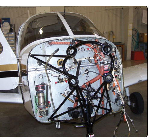
When an aircraft engine is removed and reinstalled—whether for overhaul, replacement, or major repair—the work does not stop at torquing the last engine mount bolt. Everything mounted or routed forward of the firewall must be inventoried, inspected, reinstalled correctly, and fully documented before the aircraft can legally return to service. This region, commonly called the firewall-forward area, contains the engine itself plus dozens of supporting components: fuel lines, oil lines, ignition harnesses, exhaust stacks, baffles, cooling ducts, propeller governor lines, engine controls, and more. Missing a single fitting or failing to record a replaced component can ground the aircraft, violate federal regulations, or—in the worst case—lead to an in-flight emergency.
This article walks through the systematic approach an Aviation Maintenance Technician (AMT) uses to inventory, verify, and document every firewall-forward component during engine removal and installation. It is grounded in the requirements of 14 CFR Part 43, the maintenance record-keeping provisions of 14 CFR Part 91, and the guidance found in the FAA's Aviation Maintenance Technician Handbook—Powerplant (FAA-H-8083-32).
What Lives Forward of the Firewall
The firewall itself is a certified, fireproof barrier—typically stainless steel, titanium, or other approved fireproof material capable of withstanding flame penetration for a specified time—separating the engine compartment from the cockpit or cabin structure. Every component on the engine side of this barrier is considered firewall-forward. A complete inventory must account for all of the following categories:
- Engine and engine mount: The engine assembly (including all accessories already attached), the engine mount structure, and the associated hardware (bolts, bushings, shock mounts, and safety wire).
- Fuel system components: The fuel pump (engine-driven and, where applicable, electric boost pump lines), the fuel control or carburetor, fuel injection lines or fuel nozzles, fuel flow divider or distribution valve, and all associated fittings, B-nuts, and fire-sleeve sections.
- Oil system components: The engine-driven oil pump (integral to most reciprocating engines), external oil cooler, oil cooler lines, oil temperature and pressure fittings, breather and vent lines, and the oil filler access arrangement.
- Ignition system: Both magnetos (or electronic ignition units), the ignition harnesses with individual spark plug leads, spark plugs (dual ignition with two plugs per cylinder is the standard convention on most certificated reciprocating engines, though this is a design convention rather than a fixed regulatory requirement), and the ignition switch wiring passing through the firewall.
- Exhaust system: Exhaust stacks or headers, mufflers (if cabin-heat equipped), turbocharger turbine housing (if turbocharged), exhaust gaskets, and all clamps or V-band couplings.
- Induction system: Intake manifold, carburetor heat box or alternate air door, air filter element and airbox, and any inter-cooler ducting on turbocharged engines.
- Engine controls: Throttle, mixture, propeller, and carburetor heat control cables or rods; their associated end fittings, clevis pins, and safety devices (cotter pins or clips).
- Cooling system: Cylinder baffles, blast tubes (for magnetos, oil cooler, and other accessories), inter-cylinder baffles, and cowl flap actuating rods if fitted.
- Electrical accessories: Alternator or generator (with its mounting bracket and drive belt or gear), starter motor, starter solenoid, and all associated wiring, bus connections, and bonding straps.
- Engine instrumentation fittings: Manifold pressure line, oil pressure and temperature senders, cylinder head temperature (CHT) probes, exhaust gas temperature (EGT) probes, tachometer drive cable or electronic pickup, and fuel flow sender.
- Propeller and governor: Propeller assembly, spinner and spinner bulkhead, propeller governor (if constant-speed), governor oil line, and all associated hardware.
- Fire detection and extinguishing provisions: Fire detector loops or sensing elements (if installed), fire extinguisher nozzles (if installed), and related wiring or tubing.
The Inventory Process: Step by Step
Before Removal—Creating the Baseline
Before the first bolt is loosened, the AMT should photograph and, where regulations or the manufacturer's maintenance manual require it, sketch the routing of every hose, wire bundle, and control cable in the engine compartment. These reference images become an invaluable tool during reinstallation. Many manufacturers publish a component location diagram in the aircraft maintenance manual (AMM); this diagram should be printed and kept at the workstation throughout the job.
A written parts list—either taken from the applicable Illustrated Parts Catalog (IPC) or generated from the AMM component list—serves as the master inventory sheet. Each component is checked off as it is removed and tagged with a serviceable, unserviceable, or repairable designation before it is laid out on a clean work surface. Hardware (nuts, bolts, washers, cotter pins, and safety wire) should be bagged by location; reuse of safety wire, cotter pins, and self-locking nuts is generally prohibited. The FAA-H-8083-32 stresses that all hardware removed from an engine installation must be inspected for corrosion, thread damage, and proper grade before reinstallation.
During Installation—Verification at Each Stage
Reinstallation should follow a logical sequence that avoids blocking access to later work. A typical flow is: mount the engine on the engine mount, install the exhaust system and baffles, attach major oil and fuel lines, install ignition components, attach engine controls, install electrical accessories, then finalize instrumentation lines and propeller. At each stage the AMT checks components against the parts list and confirms correct part numbers, particularly for any component that was replaced rather than reused.
Torque values are critical. The AMM specifies torque for every fastener. Engine mount hardware, for example, is typically torqued and then safety-wired or fitted with cotter pins. Spark plugs are torqued to manufacturer specification—generally cited in the range of roughly 25–30 ft-lb (approximately 300–360 in-lb) for most aviation spark plugs, depending on plug and cylinder head material, but always verify in the applicable engine and plug manufacturer's data. Over-torquing can damage plug threads in aluminum cylinder heads; under-torquing leads to hot gas leakage and plug ejection.
Final Walk-Around Inspection
Before closing the cowl, the AMT performs a methodical walk-around of the entire engine compartment, physically touching each component and verifying: correct installation, security of all fittings, presence of all required safety wire and cotter pins, absence of chafing between wire bundles and moving parts, correct routing of flexible hoses (no sharp bends or contact with hot surfaces), and correct engagement of all control cable end fittings with their respective levers or bellcranks. A second technician or inspector performing an independent inspection of the completed work—sometimes called a buy-back inspection—greatly reduces the probability of a missed item.
Documentation Requirements
Under 14 CFR Part 43.9, any maintenance, preventive maintenance, rebuilding, or alteration performed on a certificated aircraft must be recorded in the aircraft's maintenance records. For an engine removal and reinstallation, the entry must include: a description of the work performed (or a reference to the data used, such as the AMM chapter and section), the date of completion, the aircraft total time in service, the signature and certificate number of the person approving the work for return to service, and the type of certificate held (e.g., A&P, IA).
If a major repair or major alteration was performed—as defined in 14 CFR Part 43 Appendix A—an FAA Form 337 must be completed in addition to the logbook entry. Engine removal and reinstallation alone (using the same or a like-approved engine) is generally not a major alteration, but any modification to the engine mount, firewall penetrations, or fuel system routing could trigger this requirement. When in doubt, consult the local FSDO.
The engine logbook (or engine maintenance record) must also be updated. The entry should capture the engine total time since new (TTSN), time since major overhaul (SMOH), the reason for removal, any work performed on the engine while it was off the airframe, and the return-to-service signature. If a replacement engine is installed, the new engine's logbook and any 8130-3 airworthiness approval tag (for new or overhauled components) must be retained with the aircraft records.
Key Numbers and Rules
- 14 CFR 43.9: Requires a maintenance record entry for every maintenance action, including engine installation; must include description, date, aircraft time, and approving signature/certificate number.
- 14 CFR 43.13: Work must be performed using methods, techniques, and practices acceptable to the FAA—typically the manufacturer's maintenance manual or equivalent FAA-approved data.
- 14 CFR Part 43 Appendix A: Defines major repairs and major alterations requiring an FAA Form 337 in addition to a logbook entry.
- 14 CFR 43.7: Establishes who may approve an aircraft, engine, or component for return to service, including after a major repair or major alteration; a properly rated technician or an appropriately authorized IA must approve the work before flight.
- FAA-H-8083-32 guidance: Stresses use of the applicable Type Certificate Data Sheet (TCDS) and engine manufacturer's overhaul manual to verify that all installed components are the correct approved parts for that engine model and aircraft serial number.
- Cotter pins and safety wire: Single-use items—never reused after removal. MS (Military Standard) hardware specifications apply to most certificated aircraft fasteners.
Common Test Traps
- Assuming the logbook entry covers everything: The engine logbook and the aircraft airframe logbook are separate records, and both must be updated during an engine installation. Forgetting the engine logbook entry is a common oversight.
- Confusing a major repair with routine maintenance: Installing a previously overhauled engine of the same model is typically routine maintenance; modifying the engine mount or adding an unapproved accessory triggers major alteration paperwork. Know where the line is.
- Reusing safety-critical single-use hardware: Cotter pins, self-locking nuts, and safety wire must be replaced any time they are removed. The exam may present scenarios where a technician reuses a cotter pin—this is always incorrect practice.
- Overlooking fire sleeve and hose expiration: Flexible fuel and oil hoses have a life limit (time and/or calendar based) specified in the aircraft or hose manufacturer's data. An engine removal is the opportunity to inspect and replace aging hoses; ignoring this is a documentation and airworthiness error.
- Failing to record the 8130-3 tag: When a replacement engine or major accessory is installed with a Form 8130-3 airworthiness approval tag, that document must be retained in the aircraft records. Simply attaching it to the engine and closing the cowl is not sufficient record-keeping.