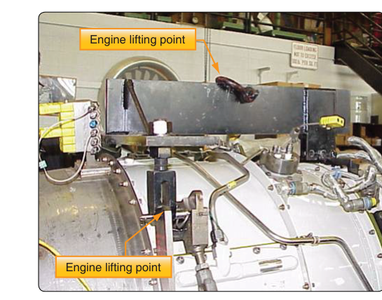
Removing and reinstalling an aircraft engine is one of the most demanding tasks an aviation maintenance technician (AMT) will perform. Unlike lifting a piece of shop equipment, hoisting a powerplant—which may weigh anywhere from a few hundred pounds for a small reciprocating engine to several thousand pounds for a turbine—demands meticulous planning before a single bolt is loosened. Two foundational decisions drive that planning: which lifting sling to use and exactly where to attach it. Get either one wrong and the consequences range from a damaged engine case to a catastrophic fall that injures personnel and destroys an irreplaceable assembly. This article covers both decisions in depth, grounded in the principles found in the FAA Aviation Maintenance Technician Handbook—Powerplant (FAA-H-8083-32).
A lifting sling in aviation maintenance is a rigging assembly—typically consisting of chains, cables, or synthetic webbing arranged in a specific geometry—designed to transfer the engine's weight to a hoist or crane while keeping the engine stable, level, and undamaged throughout the lift. Because every engine model has a unique center of gravity location and a unique arrangement of structural lugs, slings are not interchangeable between engine types without engineering authorization. The approved data governing a specific lift always comes from the engine manufacturer's maintenance manual, the aircraft manufacturer's maintenance manual, or both.
How Engine Lifting Slings Work
A lifting sling functions by distributing the engine's weight among multiple attachment points. Spreading the load reduces the stress concentration at any single lug and, more importantly, controls the attitude of the engine during the lift. A typical sling for a horizontally-opposed reciprocating engine might have two primary legs attaching forward and aft on the top of the engine case, with a spreader bar keeping the legs from collapsing inward and crushing accessories. Turbine engine slings are often three- or four-point designs because the longer, heavier assembly must be held level both fore-and-aft and laterally.
The geometry of the sling legs matters enormously. As the angle between a sling leg and the vertical increases, the tension in that leg increases dramatically. At a 30-degree angle from vertical, each leg carries approximately 1.15 times the load it would carry if perfectly vertical. At 60 degrees from vertical the factor rises to roughly 2.0 times, meaning the sling hardware and attachment lugs must be rated for twice the engine's actual weight. This is why manufacturers specify a maximum included angle for sling legs—commonly 60 to 90 degrees total (30 to 45 degrees per side from vertical)—and why using a sling that is too short can overstress both the rigging and the engine attachment lugs even though the engine hasn't moved yet.
Sling materials fall into three broad categories. Chain slings are durable and resist abrasion and heat, making them suitable for turbine work where residual heat in the nacelle is possible. Wire rope (cable) slings offer high strength-to-weight ratios but require inspection for broken wires, kinks, and corrosion before each use. Synthetic web slings (nylon or polyester) are gentle on finished surfaces and easy to inspect visually, but they can be cut by sharp edges, degraded by certain chemicals, and weakened if exposed to temperatures above their rated limits. The appropriate material choice is specified in the maintenance manual; an AMT should never substitute one type for another without approved data.
Identifying Approved Attachment Points
Aircraft and engine manufacturers engineer specific structural points to accept lifting loads. These are typically machined steel lugs, bosses, or threaded inserts built into the engine case at locations that align the sling geometry with the engine's center of gravity. They are not accessory mounting pads, rocker cover bolts, oil filler necks, or any other convenient protrusion—and this distinction trips up even experienced technicians. Attaching a sling to an unapproved location risks cracking a case, stripping threads, or causing the engine to swing out of level, potentially slamming it into the airframe.
The approved attachment points for each specific engine are identified in the applicable engine overhaul or maintenance manual and are often depicted in the aircraft's maintenance manual as well. Some engines have permanent, captive lugs marked with color coding or placards. Others require the installation of lifting adapter fittings—threaded inserts or bolts supplied with or called out by the sling kit—that engage specific tapped holes in the case. These adapter fittings must be fully threaded in and torqued to the value specified in the manual before any load is applied. Partial thread engagement is a leading cause of lug pull-out during engine lifts.
Before any engine removal begins, the AMT should perform the following verification steps with the maintenance manual open:
- Identify the specific engine model and configuration — even minor sub-variants may have different lug locations or require different adapter hardware.
- Confirm the correct sling part number — manufacturer-approved sling assemblies are often listed in the illustrated parts catalog or the removal/installation section of the maintenance manual.
- Inspect every sling component — check chains for elongated or cracked links, wire rope for broken wires or kinks, synthetic webbing for cuts, fraying, UV degradation, or chemical staining; verify that all hooks have functioning safety latches and that master links, shackles, and spreader bars are intact and not deformed.
- Check sling capacity ratings — each sling assembly carries a working load limit (WLL) stamped or tagged on the hardware. The WLL must exceed the engine's listed weight with an adequate safety margin; typical shop practice and the sling manufacturer's guidance call for a WLL of at least twice the actual load.
- Verify hoist capacity — the overhead hoist or engine stand crane must also be rated for the load, and its attachment to the facility structure must be verified as adequate.
Why It Matters — Safety and Regulatory Perspective
The FAA Aviation Maintenance Technician Handbook—Powerplant makes clear that engine removal and installation must be accomplished in accordance with the aircraft manufacturer's maintenance instructions and, where applicable, the engine manufacturer's overhaul manual. This is not merely procedural guidance—it is the foundation of an airworthiness determination. An engine that has been dropped, even if it appears undamaged, has been subjected to an unmeasured shock load. Such an event must be reported, and the engine must be inspected in accordance with the manufacturer's guidance before it can be returned to service. The cost of that inspection and potential scrapping of the engine far exceeds any time saved by skipping sling verification steps.
From a personnel safety standpoint, OSHA regulations (which apply in the maintenance shop environment) independently require that all lifting equipment be rated for the load, inspected before use, and used in accordance with the manufacturer's limits. The FAA's regulatory framework under 14 CFR Part 43 requires that maintenance be performed in a manner that results in an airworthy product; using wrong or degraded sling equipment is a direct violation of that standard. An AMT who improvises a lift risks both criminal liability and the revocation of their certificate.
Key Numbers and Rules
- Maximum sling leg angle: Typically 60–90 degrees total included angle (30–45 degrees per side from vertical); always verify the specific limit in the applicable maintenance manual.
- Thread engagement: Lifting adapter fittings must be fully seated and torqued to the specified value — never estimate thread engagement by feel.
- Working load limit: The sling WLL must meet or exceed the engine weight; manufacturer guidance and sound shop practice generally call for a minimum 2:1 safety factor.
- Pre-use inspection: Every sling component must be inspected before each lift — not just at the beginning of the workday.
- Approved data required: The specific sling part number and attachment procedure must come from the engine or aircraft manufacturer's current approved documentation, not from memory or assumed similarity to another model.
- Synthetic webbing temperature limits: Nylon and polyester slings typically must not be used above 194°F (90°C); always check the sling tag for the rated limit before using near a recently-run engine.
Common Test Traps
- Assuming slings are universal. FAA test questions often present a scenario where a technician uses a sling from a similar engine. The correct answer is always that the specific approved sling or an equivalent approved by the manufacturer is required — there is no universal engine sling.
- Confusing rated load with actual load. A sling rated at 2,000 lb does not mean it can safely lift a 2,000 lb engine at a 60-degree leg angle. The leg angle multiplier must be accounted for; the effective load on each leg rises with the angle.
- Ignoring adapter fitting torque. Test questions may ask what happens if lifting adapters are not fully torqued. The answer is thread pull-out and potential engine drop — partial engagement dramatically reduces holding strength.
- Selecting attachment points by convenience. Exam scenarios frequently describe a technician attaching to an accessible bolt or bracket. The correct action is always to consult the maintenance manual and use only the manufacturer-specified structural lifting lugs.
- Skipping sling inspection because the sling was just used. The FAA expects a pre-use inspection every time. A wire rope sling can develop a broken wire or a synthetic sling can acquire a cut during handling between uses.