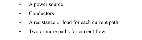
Every aircraft electrical system is built around the fundamental principle that components must receive the correct voltage and current to operate reliably. Understanding how parallel circuits behave is therefore one of the most practical skills an Aviation Maintenance Technician (AMT) can develop. Unlike series circuits, where a single break stops all current flow, a parallel circuit provides multiple independent paths for electrons to travel. This redundancy is not accidental — aircraft designers deliberately use parallel wiring to keep critical systems alive even when one branch fails.
This article covers the mechanics of parallel circuits, the mathematics of resistance calculation, why total resistance behaves so counterintuitively, and the real-world implications for inspection and repair. Whether you are preparing for the FAA Aviation Mechanic General knowledge test or trying to make sense of an aircraft wiring diagram, mastering parallel circuits pays dividends every day on the job.
How Parallel Circuits Work
In a parallel circuit, two or more components are connected across the same two points in a circuit, meaning each component shares the same voltage source directly. Every branch has its own current path that runs from one terminal of the source, through the component, and back to the other terminal. Because of this arrangement, the voltage across every branch is identical and equals the source voltage.
Current, however, divides among the branches. Ohm's Law (I = E ÷ R) tells us that each branch draws its own independent current based solely on that branch's resistance. A branch with lower resistance draws more current; a branch with higher resistance draws less. The total current supplied by the source is the sum of all individual branch currents:
- Itotal = I1 + I2 + I3 + …
This is a direct consequence of Kirchhoff's Current Law, which states that the total current entering any junction equals the total current leaving it. No electrons are created or destroyed at a junction — they simply redistribute among the available paths.
Calculating Total Resistance in a Parallel Circuit
Here is where many students are surprised: adding more branches to a parallel circuit decreases total resistance. Each new path gives electrons an additional route, so the overall opposition to current flow goes down. The formula for total parallel resistance reflects this:
- 1 ÷ Rtotal = (1 ÷ R1) + (1 ÷ R2) + (1 ÷ R3) + …
After summing the reciprocals, you take the reciprocal of the result to get Rtotal. A useful rule of thumb: Rtotal is always less than the smallest individual branch resistance. If you calculate a total resistance larger than any single branch, you have made an arithmetic error — check your work.
Worked Example: Two Resistors in Parallel
Suppose you have a 12-volt aircraft bus powering two parallel loads: a 6-ohm cabin light circuit (R1) and a 12-ohm avionics fan (R2). First, find Rtotal:
- 1 ÷ Rtotal = (1 ÷ 6) + (1 ÷ 12) = 0.1667 + 0.0833 = 0.25
- Rtotal = 1 ÷ 0.25 = 4 ohms
Notice that 4 ohms is less than either 6 or 12 ohms. Now find each branch current and total current using Ohm's Law (I = E ÷ R, with E = 12 V):
- I1 = 12 ÷ 6 = 2 amperes
- I2 = 12 ÷ 12 = 1 ampere
- Itotal = 2 + 1 = 3 amperes
You can verify: Itotal = E ÷ Rtotal = 12 ÷ 4 = 3 A. The math checks out perfectly.
Special Case: Two Equal Resistors in Parallel
When exactly two resistors of the same value (R) are wired in parallel, total resistance is simply R ÷ 2. Three equal resistors give R ÷ 3, and so on. This shortcut is fast and reliable during knowledge-test calculations when the values happen to match.
The Product-Over-Sum Shortcut
For any two resistors in parallel (even unequal ones), you can use the product-over-sum formula as an alternative:
- Rtotal = (R1 × R2) ÷ (R1 + R2)
Using the example above: Rtotal = (6 × 12) ÷ (6 + 12) = 72 ÷ 18 = 4 ohms. Same answer, fewer steps — handy for a two-branch problem on the test or ramp.
Why Parallel Circuits Matter in Aircraft Systems
Aircraft designers choose parallel wiring for several important reasons rooted in safety and function. First, fault isolation: if one parallel branch develops an open (broken wire, blown fuse, failed component), current continues to flow through all other branches uninterrupted. A landing light burning out does not extinguish the navigation lights wired on the same bus because each light is its own independent branch.
Second, voltage consistency: every load in the aircraft — from avionics to cockpit lighting — needs the correct operating voltage. Because all parallel branches see the same voltage, designers can connect components with different current demands to the same bus without affecting each other's voltage supply.
Third, load management: as technicians add or remove loads from a parallel bus, total resistance changes, which changes total current draw from the source. This is why generator and alternator capacity must be matched to the total expected parallel load. An overloaded bus that draws more current than the alternator or wiring can handle leads to overheating, insulation damage, and potential fire — a critical safety concern addressed throughout the FAA Aviation Maintenance handbooks.
From a troubleshooting standpoint, an AMT must recognize that a short circuit in any one parallel branch dramatically lowers total resistance, causing total current to spike. This is why circuit protection devices (circuit breakers and fuses) are wired in series with each parallel branch: to isolate the faulted branch before excess current damages the source wiring or starts a fire.
Key Numbers and Rules
- Voltage is the same across all branches in a parallel circuit and equals the source voltage.
- Total current equals the sum of all branch currents: IT = I1 + I2 + I3 + …
- Total resistance is found using the reciprocal formula: 1 ÷ RT = Σ(1 ÷ Rn).
- Rtotal is always less than the smallest individual branch resistance.
- Two equal resistors in parallel: RT = R ÷ 2.
- Two unequal resistors in parallel: RT = (R1 × R2) ÷ (R1 + R2).
- Adding a branch decreases Rtotal and increases Itotal.
- Removing a branch (open circuit) increases Rtotal and decreases Itotal, but all remaining branches continue at the same voltage.
Common Test Traps
- Confusing total resistance direction: Students expect that adding more resistors increases total resistance (as in series circuits), but in parallel circuits the opposite is true — every added branch lowers Rtotal. If your calculated answer is larger than any single branch resistor, you have made an error.
- Forgetting the reciprocal step: After summing the reciprocals (1÷R1 + 1÷R2 + …), you must take the reciprocal of that sum to get Rtotal. Skipping this final step and treating the summed fraction directly as resistance is the most common arithmetic mistake on parallel circuit problems.
- Assuming a branch failure stops all current: An open in one parallel branch only stops current in that branch. The remaining branches continue to operate normally at the same voltage. This is the opposite of what happens in a series circuit, where one open kills all current.
- Voltage misconception across branches: Some students assume voltage divides among parallel branches the way it divides among series resistors. It does not — every branch in a parallel circuit sees the full source voltage regardless of its individual resistance.
- Short-circuit current spike: If a branch resistance drops to near zero (a short), Rtotal plummets and Itotal can become dangerously high — even if all other branches are normal. The FAA knowledge test may ask why a short in one parallel branch can overload and damage the common bus wiring while leaving other branch voltages seemingly unchanged.