When an aircraft technician installs a rivet, the quality of the hole it sits in determines much of the joint's strength. A ragged, oversized, or misaligned hole concentrates stress at exactly the wrong place, inviting fatigue cracks in an environment where vibration is relentless and loads are cyclic. Similarly, when flush (countersunk) rivets are used on smooth aerodynamic surfaces, the sheet metal must be precisely formed around the rivet head — either by machine countersinking or by a deformation process called dimpling. Understanding the correct methods, tools, and tolerances for both hole preparation and dimpling is fundamental to any airframe sheet metal repair and is heavily tested on the FAA Aviation Mechanic Airframe knowledge examination.
This article walks through the complete process: from laying out and drilling pilot holes, to reaming to final size, to deburring, and finally to the two primary methods of preparing flush rivet seats — countersinking and dimpling. Each step has specific FAA-accepted procedures documented in the Aviation Maintenance Technician Handbook — Airframe (FAA-H-8083-31).
Rivet Hole Layout and Initial Drilling
Before any drill touches the metal, the technician must establish correct edge distance and spacing. Edge distance is the distance from the center of the rivet hole to the nearest edge of the sheet. The minimum acceptable edge distance is typically two times the rivet shank diameter (2D). Placing holes closer to an edge than this leaves too little material to transfer load and greatly increases the risk of the sheet tearing out through that edge. Rivet spacing (pitch) in a single row is generally a minimum of three times the diameter (3D), while the transverse distance between rows is typically 2.5D minimum. These dimensions are set by the original design or the applicable Structural Repair Manual (SRM) for the aircraft — the technician must always match the original pattern unless engineering approval exists for a deviation.
Drilling begins with a pilot hole, which is always smaller than the final rivet hole. Drilling in two stages — pilot then final — prevents the drill from wandering on curved or multilayer structures and reduces heat buildup that can work-harden aluminum. For most rivet installations the drill is chosen to produce a hole that matches the rivet shank diameter as closely as possible; the fit should be snug but allow the rivet to be inserted by hand without forcing. A hole that is too tight will distort the sheet when the rivet is driven; one that is too loose allows the rivet shank to buckle rather than fill the hole uniformly, reducing shear strength.
When drilling through multiple layers — such as a skin over a stringer over a frame — the layers must be clecoed together before drilling begins. Clecos are spring-loaded fasteners that hold sheets in alignment; a common practice is to install a cleco in every third or fourth hole as drilling progresses so the stack does not shift. Drilling through unsecured stacks almost always results in misaligned holes that create stress risers and may require the joint to be completely re-drilled oversize, potentially calling for an oversize rivet or a complete patch repair.
Drill Selection and Feed Rate
The correct drill for most aluminum sheet work is a 118-degree high-speed steel twist drill, though some technicians prefer a 90-degree included angle for thin sheet to reduce burr formation. Drilling speed should be high, and feed pressure should be light and steady. Pushing too hard causes the drill to grab as it breaks through the far side, producing a large exit burr and sometimes cracking the sheet. Using a drill stop or depth collar is good practice on thin skins to prevent the drill from plunging through and damaging underlying structure.
Reaming to Final Size
For precision work, after the pilot hole is drilled, a rivet hole reamer is used to bring the hole to its final, exact diameter. Reaming removes only a small amount of material but produces a much smoother hole wall than drilling alone. A smooth hole wall is important because microscopic tool marks left by a drill bit act as stress concentration points — tiny notches from which fatigue cracks can propagate under repeated loading. Reaming also produces a more consistent hole diameter across the entire depth of the hole, which is critical when thick stacks are being riveted.
Deburring
After drilling (and reaming), every hole must be deburred on both sides. Burrs are thin slivers of metal curled up at the edges of the hole by the drilling action. If left in place, burrs prevent the sheets from seating flush against each other, create a stress concentration point at the hole edge, and can cut through protective coatings. A countersink bit rotated lightly by hand (never power-driven for deburring) or a dedicated deburring tool removes the burr and leaves a slight chamfer that guides the rivet in. The chamfer should be just enough to eliminate the burr — perhaps 0.005 to 0.010 inches — not a full countersink. Over-deburring removes load-bearing material and defeats the purpose.
Countersinking vs. Dimpling
Flush rivets — most commonly the 100-degree AN426 series — require the material around the hole to be shaped so the rivet head sits perfectly flush with the outer surface. There are two approved methods to accomplish this: machine countersinking and dimpling.
Machine Countersinking
Machine countersinking uses a piloted countersink cutter (often called a microstop countersink) to cut a conical recess directly into the surface of the material. The pilot rides in the hole to keep the cutter centered, and a depth stop controls exactly how deep the cone is cut. The resulting countersink angle must match the rivet head angle — for AN426 rivets this is 100 degrees. The depth is correct when the rivet head sits flush: not proud of the surface (which creates aerodynamic drag and a stress concentration) and not below the surface (which leaves a depression and a thin, weakened rim of metal).
Machine countersinking is appropriate when the material is thick enough that cutting the conical recess still leaves adequate material below the head. The FAA guidance in FAA-H-8083-31 establishes that when the sheet is so thin that countersinking would leave a knife-edge condition — less than approximately 0.020 inches of remaining material below the countersink — machine countersinking alone is not acceptable. In practice, machine countersinking of the outer skin is often combined with a dimpled inner layer (called a countersunk dimple or back-dimple), but the key principle is: if countersinking would knife-edge the sheet, dimpling must be used instead.
Dimpling
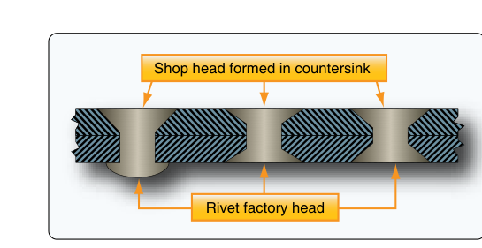
Dimpling uses matching male and female dimple dies to cold-form a conical depression in the sheet metal without removing any material. The metal is simply displaced into the die shape. Because no material is removed, dimpling can be used on thin sheets where countersinking would create a knife-edge. Dimpling also work-hardens the metal slightly around the hole, which can improve fatigue life at that location.
There are three main dimpling methods:
- Coin dimpling (hand dimpling): A male die is placed through the hole from one side and a female die on the other; a hammer or squeezer presses them together. Simple and common for thin aluminum skins in the 0.016–0.040 inch range.
- Radius dimpling: Uses dies with a slightly radiused (rounded) transition at the base of the cone rather than a sharp angle. This reduces cracking tendencies in harder aluminum alloys such as 2024-T3 that are prone to cracking when sharply formed.
- Hot dimpling: The metal is heated before forming, reducing the risk of cracking in very hard or thick materials. Used for alloys that cannot be cold-dimpled without risk of fracture.
The dimple must be sized so it accepts the rivet head flush with the surface. When a dimpled skin overlies a dimpled substructure, the dimples must nest tightly — a poorly formed dimple leaves a gap between layers that acts as a stress riser and may allow moisture intrusion.
Why Proper Technique Matters
Aircraft skin joints are fatigue-critical. Every flight cycle pressurizes and depressurizes a fuselage, flexes wings, and subjects the entire structure to vibration. A hole drilled off-center, left with a burr, countersunk too deep, or dimpled with a cracked edge is a site waiting to initiate a fatigue crack. FAA accident records and airworthiness directives repeatedly trace structural failures back to improper fastener hole preparation during maintenance or repair. The cost of doing it right — taking a few extra minutes to ream, deburr carefully, and check countersink depth with a rivet and straightedge — is trivially small compared to the consequence of getting it wrong.
Key Numbers and Rules
- Minimum edge distance: 2D (two times rivet diameter) from hole center to sheet edge.
- Minimum pitch (rivet spacing): 3D center to center in the same row.
- Flush rivet head angle (AN426): 100 degrees — countersink and dimple dies must match.
- Knife-edge threshold: If countersinking leaves less than approximately 0.020 inches of material below the head, dimple instead.
- Deburring chamfer: Light, hand-applied — approximately 0.005–0.010 inches — not a full countersink.
- Hole fit: Snug — rivet should slide in by hand but not rattle; oversized holes reduce joint shear strength significantly.
- Dimpling alloy consideration: 2024-T3 and similar hard alloys may require radius or hot dimpling to avoid cracking.
Common Test Traps
- Confusing edge distance and pitch: Edge distance is 2D (hole center to edge), pitch is 3D (hole center to hole center). The FAA knowledge test often presents these values interchanged — know which is which.
- Assuming countersinking always works: When sheet is thin enough to knife-edge, dimpling is required. The test may present a scenario with thin skin and ask which method is appropriate.
- Forgetting to deburr both sides: The question may ask about deburring procedure — the correct answer is both sides of every hole, every time.
- Confusing the rivet head angle: AN426 flush rivets are 100 degrees. AN470 universal head rivets do not require countersinking or dimpling at all — mixing these up on the test is a common error.
- Over-countersinking: A countersink that is too deep leaves a thin, weak rim (knife-edge), while a countersink that is too shallow leaves the rivet head proud of the surface. Both conditions are rejectable — the test may ask which is more detrimental, and the answer is the knife-edge (structural failure risk) versus the proud head (aerodynamic and stress issue).