Two of the most recognizable features on an aircraft's internal sheet metal structure are the joggle joint and the flanged lightening hole. Both appear frequently on ribs, bulkheads, frames, and skin doublers, and understanding why they exist — not just what they are — separates a skilled airframe technician from someone who is merely following instructions. This article explains the geometry, the fabrication process, and the structural logic behind each feature, with the detail you need to pass the FAA Aviation Mechanic written test and to do quality work on the shop floor.
What Is a Joggle Joint?
A joggle (sometimes called an offset or jog) is a deliberate, step-like offset formed into a piece of sheet metal so that two overlapping pieces can lie in the same plane at their mating surfaces. Without a joggle, whenever one sheet overlaps another there would be a bump or a ridge at every lap joint — think about stacking two pieces of cardboard and how the top piece sits higher than the surrounding surface. In airframe construction that offset creates unfair surfaces, stress concentrations, and fitment problems.
The joggle solves this elegantly. One of the two mating parts is offset by exactly the thickness of the other part (or the thickness of the overlap plus any sealant or shim allowance), so that when they are assembled the outer surfaces are flush and the load path is smooth and continuous. Joggle joints are extremely common where skin sheets meet stringers, where a rib flange slides under a skin, or where a repair doubler must blend into the original skin surface without creating a proud edge.
Joggle Geometry and Dimensions
The critical dimensions of a joggle are the depth (equal to the material thickness being accommodated), the radius at each bend, and the flat between the two bends (called the joggle length or offset length). The two bends that form a joggle are parallel and equal in magnitude but opposite in direction. The radius at each bend must be generous enough to avoid cracking the material — the FAA Aviation Maintenance Technician Handbook: Airframe (FAA-H-8083-31) specifies that bend radii must conform to the minimum bend radius tables for the specific alloy and temper, just as with any other formed bend in sheet metal. Aluminum alloys in hard tempers such as 2024-T3 require larger minimum bend radii relative to material thickness than softer alloys or pure aluminum.
The joggle length (the flat between the two offset bends) should be long enough to allow full-contact seating of the mating part and to distribute the load over a reasonable area. If the joggle is too short, the transition is too abrupt and stress risers develop at each bend. If it is too long, material is wasted and the part becomes unnecessarily heavy. Manufacturers publish joggle dimensions in their structural repair manuals (SRMs), and the technician must match those dimensions exactly in repair work.
Fabricating a Joggle
Small joggles are formed with a joggle die set in a hydraulic or hand-operated press, or with specialized joggle pliers for narrow flanges. The die set creates both offset bends simultaneously, ensuring that they are perfectly parallel and that the depth is consistent along the full length of the joggle. For longer joggles on wide parts, a press brake fitted with offset punches and dies may be used, working the joggle in a single press stroke across the full length of the flange.
When a joggle must be made in the field or in a repair shop without specialized tooling, the technician can form each bend individually on a cornice brake, carefully measuring and indexing the part for each pass. This approach demands precise layout and careful attention to springback. The finished joggle must be checked against the original part or the SRM dimension with calipers and a straightedge to confirm that the offset depth is correct and that the surfaces are truly flat when mated.
What Is a Flanged Lightening Hole?
A lightening hole is a cutout in a rib web, bulkhead, or other internal structural member that removes material (and therefore weight) from an area that contributes little to the member's load-carrying ability. The concept follows directly from stress analysis: a rib web in bending carries most of its shear load near the caps (flanges), and the material near the neutral axis of the web contributes proportionally less. Removing that low-stress material saves weight without seriously reducing strength.
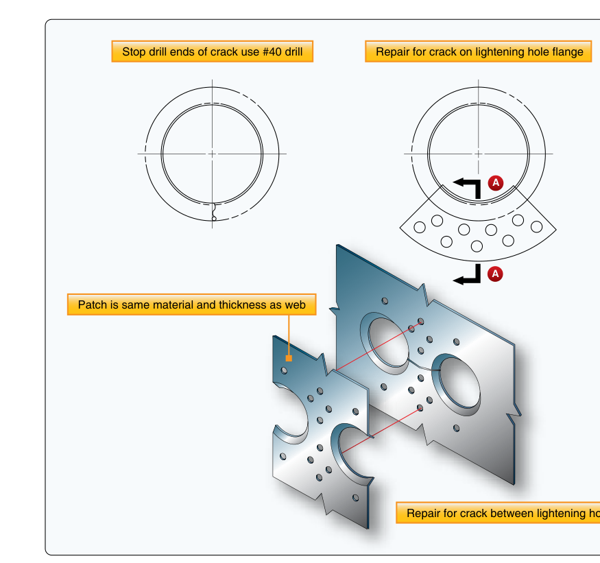
However, a plain circular hole in a sheet introduces a stress concentration factor — the edges of the hole attract stress, and without reinforcement the remaining metal around the hole can crack under repeated loading. The solution is to flange the lightening hole: the metal around the cutout is bent perpendicular to the web, forming a short cylindrical lip (the flange) that stiffens the edge of the hole and restores much of the original section stiffness. This flanged edge acts like a miniature rim, resisting the tendency of the hole to distort under shear and bending loads.
Geometry of the Flanged Lightening Hole
The flange on a lightening hole is characterized by its flange height (how far the lip projects from the web surface) and the flange angle (typically 90 degrees to the web). Standard flanged lightening holes also incorporate a radius at the bend between the web and the flange, because a sharp corner at the base of the flange would itself become a stress riser. FAA-H-8083-31 does not itself publish a numeric minimum flange-height ratio; specific flange height requirements are set by the manufacturer's engineering data and structural repair manual (SRM) for the particular part. The diameter of the hole itself is governed by the structural requirements and the part dimensions.
Many aircraft parts use a beaded lightening hole as an alternative, where instead of a full 90-degree flange a shallow bead (a rolled or pressed ridge) is formed around the perimeter of the cutout. The bead accomplishes a similar stiffening effect and is easier to form in some geometries. Whether a flanged or beaded treatment is used depends on the specific structural and manufacturing requirements of the part, as called out in the manufacturer's drawings and SRM, rather than a universal rule favoring one over the other.
Fabricating a Flanged Lightening Hole
Flanged lightening holes are typically formed in two steps. First, a pilot hole is drilled or punched at the correct location, slightly smaller than the finished hole diameter. Then the hole is either dimpled and drawn using a flanging punch and die set, or spun outward progressively with a flanging tool. The flanging operation stretches the metal at the edge of the hole, drawing it into the perpendicular flange. Because the metal is being stretched (not bent in a straight line), it is subject to cracking if the alloy is too hard, if the forming is done too rapidly, or if the hole edge has burrs or nicks that act as crack initiators.
Before flanging, the pilot hole must be carefully deburred and the edges must be smooth. Tooling marks, scratches, or burrs on the edge of the hole will propagate into cracks during the flanging operation. After flanging, the technician inspects the flange with a magnifying glass and, if required by the maintenance manual, applies a dye-penetrant inspection to confirm that no cracks have formed at the base of the flange.
Why These Features Matter
Both joggles and flanged lightening holes reflect the fundamental philosophy of aircraft structural design: carry the required loads with the least possible weight, and maintain a smooth, continuous load path without stress concentrations. A joggle that is too shallow leaves a proud edge that can tear under vibration; one that is too deep or has too sharp a bend can crack the part during fabrication or in service. A flanged lightening hole whose flange is too short offers little stiffening benefit; one that is cracked at the base becomes a fatigue initiation site that can propagate through the web.
In repair work, regulations require that replacement parts match the original in material, heat treat condition, and forming geometry. A technician who flattens a joggle to make a part easier to fit, or who skips the flanging step on a lightening hole, has changed the structural characteristics of the assembly — a deviation that must be approved or that may render the repair non-airworthy.
Key Numbers and Rules
- Joggle depth must equal the thickness of the mating part (plus sealant or shim allowance as applicable).
- Bend radii for joggles must meet the minimum bend radius requirements for the specific alloy, temper, and thickness — found in bend radius tables in FAA-H-8083-31 and the applicable SRM.
- Flange height on lightening holes is set by the manufacturer's SRM or engineering data for the specific part; FAA-H-8083-31 does not publish a generic numeric multiplier for flange height.
- The pilot hole for a flanged lightening hole must be smaller than the finished hole diameter to leave material for the flanging stretch — the exact amount depends on flange height and material.
- All hole edges must be deburred before flanging to prevent crack initiation during forming.
- Cracked flanges or cracked joggle bends are not acceptable; the part must be remade or a deviation approved by the responsible engineering authority.
- Repair joggles and flanged holes must match the original drawing dimensions — improvised changes to geometry are not airworthy without engineering approval.
Common Test Traps
- Confusing joggle depth with material thickness: The joggle offset equals the thickness of the part being overlapped, not necessarily the thickness of the joggled part itself. When two different gauges are used, the joggle depth matches the thicker overlapping part.
- Ignoring minimum bend radius on joggles: Because a joggle involves two bends close together, students sometimes assume the radius rules are relaxed. They are not — each bend in a joggle must still meet the minimum bend radius for the alloy and temper.
- Believing that any hole in a rib web must be flanged: While lightening holes are almost always flanged in primary structure, access holes and drain holes in secondary structure may be plain-cut and simply deburred; always consult the drawing and SRM to determine what is required.
- Forming a flanged lightening hole without deburring first: This is a procedural error worth remembering for the FAA written test — burrs at the edge of the pilot hole cause cracks during the flanging stretch.
- Assuming a cracked flange can be blended out: A crack at the base of a lightening hole flange is a stress riser in a dynamically loaded member. Blending (filing or sanding away the crack) removes material and does not restore the original strength — the part must be replaced or the damage disposition approved by engineering.