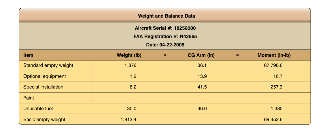
Weight and balance is one of the most safety-critical responsibilities shared between the pilot in command and the aircraft dispatcher. An aircraft loaded outside its approved center-of-gravity (CG) envelope or above its maximum allowable weight may be impossible to control, may stall at unexpectedly high speeds, or may fail structurally during normal operations. For the dispatcher, weight and balance is not an academic exercise — it is a legal and operational prerequisite before a flight can be released under 14 CFR Part 121.
This article walks through the foundational concepts — center of gravity, mean aerodynamic chord (MAC), and loading index systems — with enough mechanical detail to let a dispatcher both compute a basic problem and catch an error in a crew-submitted load sheet. The governing reference is the FAA Weight and Balance Handbook (FAA-H-8083-1), supplemented by the weight and balance performance requirements of 14 CFR 121.189 through 121.197.
Center of Gravity: The Balancing Point
The center of gravity is the single point through which the total weight of the aircraft acts downward. Engineers determine CG by taking the sum of all individual weights multiplied by their moment arms (distances measured from a fixed reference point called the datum) and dividing that total moment by the total weight. The formula is straightforward:
CG location = Total Moment ÷ Total Weight
The datum is an arbitrary reference plane — often the nose of the aircraft, the firewall, or a point ahead of the aircraft — established by the manufacturer in the Type Certificate Data Sheet (TCDS). Every item loaded aboard has a station number, which is simply its distance (in inches) aft of the datum. A seat at station 300 is 300 inches aft of the datum.
Moments are computed by multiplying each weight by its station: a 200-pound passenger seated at station 400 contributes a moment of 80,000 inch-pounds. Summing all moments and dividing by total weight gives the CG station in inches. The dispatcher then checks that this station falls within the forward and aft CG limits published in the Aircraft Flight Manual (AFM) for the applicable weight.
Why CG Limits Are Envelope-Shaped
CG limits are not a single number — they vary with gross weight, which is why they are expressed as an envelope on a graph of CG versus weight. The forward limit is driven primarily by elevator authority: if the CG is too far forward, the elevator may not have enough power to raise the nose during rotation on takeoff or to flare for landing. The aft limit is driven by longitudinal stability: a CG too far aft reduces the restoring moment that returns the aircraft to level flight after a pitch disturbance, eventually making the aircraft unstable and potentially uncontrollable.
Operating near the aft limit reduces longitudinal stability and increases the risk of an inadvertent stall or departure from controlled flight. Operating near the forward limit increases control forces, lengthens takeoff roll, raises stall speed slightly, and degrades fuel efficiency because more nose-up elevator (or stabilizer) trim is required to maintain level flight. Neither extreme is desirable; dispatchers must ensure the CG is comfortably within limits at all phases of flight — not just at departure.
Mean Aerodynamic Chord and Percent MAC
For large transport-category aircraft, CG is commonly expressed as a percentage of the mean aerodynamic chord (%MAC) rather than as a station in inches. This is because MAC-referenced limits transfer more intuitively between variants of an aircraft family and are directly meaningful to aerodynamicists and autopilot logic.
The mean aerodynamic chord is the chord length of a theoretical rectangular wing that would have the same aerodynamic pitching-moment characteristics as the actual (often tapered or swept) wing. The leading edge of the MAC (LEMAC) and trailing edge of the MAC (TEMAC) are published in the AFM and in the aircraft's weight and balance manual.
To convert a CG station (in inches) to percent MAC, apply this formula:
%MAC = [(CG station − LEMAC) ÷ MAC length] × 100
For example, if LEMAC is at station 860, MAC length is 180 inches, and the computed CG is at station 905: %MAC = [(905 − 860) ÷ 180] × 100 = 25% MAC. The AFM might list the forward limit as 15% MAC and the aft limit as 35% MAC at max gross weight, so a CG at 25% MAC would be acceptable.
Dispatchers working large jet equipment will see %MAC limits stated in the Load and Trim Sheet, and they must be able to verify that the final CG percentage falls within the envelope before signing the aircraft release.
The Loading Index System
Computing raw moments in inch-pounds for every payload change would be tedious and error-prone on the ramp. Airlines therefore use a loading index (sometimes called a load index or moment index) system, which simplifies the arithmetic by dividing moments by a large reduction factor. Typical reduction factors are 1,000 or 10,000, producing small, manageable index numbers.
Each item — basic operating weight, fuel, passengers by zone, cargo by compartment — has a published index unit contribution. The dispatcher or load planner adds these index units to the basic index, plots the final weight against the final index on a pre-printed graph (the loading envelope or trim sheet), and visually confirms that the plotted point falls inside the approved envelope. This process is fast, auditable, and minimizes arithmetic errors.
Many modern airlines use electronic load planning systems (e-LPS) that perform these calculations automatically and generate a computerized load sheet transmitted to the cockpit. Even so, the dispatcher must understand the underlying logic to catch system errors, incorrect passenger counts, or misrouted cargo that could shift CG unexpectedly.
Fuel Burn and CG Shift
CG does not remain static during flight. As fuel burns, the CG shifts because fuel tanks are rarely located exactly at the CG. Wing tanks that are ahead of or behind the CG will cause forward or aft CG movement as fuel depletes. Center tanks, which may be close to the CG, have a smaller effect. Some aircraft, notably certain Airbus models, use trim tanks in the horizontal stabilizer and automated fuel transfer to optimize CG during cruise for fuel efficiency.
The dispatcher must verify not only the departure CG but also the landing CG (with minimum fuel aboard) and, where required by the AFM or airline operations specifications, the CG at other critical phases. The weight and balance release must reflect conditions across the entire flight.
Regulatory Requirements Under 14 CFR Part 121
Under Part 121, the certificate holder is required to operate each aircraft within the weight and CG limits established by the TCDS and AFM. Sections 121.189 through 121.197 address en-route, takeoff, and landing performance limits that presuppose the aircraft is properly loaded. Critically, 14 CFR 121.693 requires that a load manifest containing weight and balance data be prepared for each flight, and 14 CFR 121.665 places joint responsibility for this on the aircraft dispatcher and pilot in command — neither may release or accept a flight they know to be in violation of weight or balance limits.
The airline must hold FAA-approved weight and balance procedures in its Operations Specifications (OpSpecs), and the dispatcher must follow those procedures exactly. Any change to loading after the load sheet is issued — a last-minute cargo addition, a passenger count change at the gate, or fuel uplifted beyond the planned quantity — requires a revised weight and balance computation before release.
Key Numbers and Rules
- %MAC formula: %MAC = [(CG − LEMAC) ÷ MAC] × 100
- Basic Operating Weight (BOW): aircraft empty weight plus crew, crew baggage, catering, and unusable fuel — everything on board before revenue payload.
- Zero Fuel Weight (ZFW): BOW plus all revenue payload; no usable fuel included. ZFW must not exceed the Maximum Zero Fuel Weight (MZFW) limit.
- Operating Weight (OW): ZFW plus usable fuel. Must not exceed Maximum Takeoff Weight (MTOW) or Maximum Landing Weight (MLW) at the applicable phase.
- Moment Index: actual moment ÷ reduction factor (commonly 1,000 or 10,000) — keeps numbers manageable on manual trim sheets.
- Forward CG limit: set by elevator/stabilizer authority; violation can prevent rotation or flare.
- Aft CG limit: set by longitudinal stability; violation risks loss of control.
- Joint responsibility: both the dispatcher and PIC must sign off that weight and balance is within limits before departure under Part 121.
Common Test Traps
- Adding weight increases moment, but CG direction depends on location. Adding weight forward of the current CG moves CG forward; adding aft moves it aft. Many students assume all added weight shifts CG aft.
- ZFW limit is structural, not aerodynamic. The MZFW limit protects the wing root from bending loads caused by fuel-less wing weight at high payload; exceeding it can cause structural damage even if gross weight is within limits.
- CG limits change with weight. A CG that is within limits at MTOW may be out of limits at a lighter landing weight. Always check the envelope at the applicable weight, not just at one reference point.
- Fuel burn can push CG out of limits mid-flight. Departure CG within limits does not guarantee landing CG within limits. The dispatcher must verify both endpoints.
- The index system is a simplification, not an approximation. Index units are derived from exact moments; the reduction factor cancels out in the graph, so the result is exact — students sometimes treat it as an estimate.