One of the most critical responsibilities of an Aviation Maintenance Technician (AMT) is the accurate identification of structural defects before they compromise the airworthiness of an aircraft. Cracks, corrosion, and fatigue damage are the three most common and consequential defect categories encountered in routine and scheduled inspections. Missing or misidentifying any one of them can lead to catastrophic structural failure — making defect identification not just a test topic, but a genuine life-safety skill.
This article walks through the mechanics of each defect type, how to recognize them visually and with inspection aids, what the FAA handbooks say about classification and action criteria, and what common knowledge-test traps await the unwary student.
Understanding Cracks
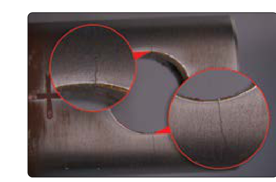
A crack is a complete or partial fracture through material that reduces its load-carrying capability. In aircraft structures, cracks almost never appear without cause. They originate from one or more of three conditions: stress concentration at a geometric feature (a hole, a notch, or a sharp radius), an overload event that exceeded the material's yield strength, or the accumulative effect of repeated cyclic loading known as fatigue — addressed separately below.
Cracks in metallic structures are classified by their orientation relative to the applied load. A transverse crack runs perpendicular to the primary stress direction and is generally the most dangerous because it directly reduces the effective cross-section carrying the load. A longitudinal crack runs parallel to the primary stress and may be less immediately critical in some structures, but still requires immediate evaluation. Diagonal or shear cracks develop at roughly 45 degrees and indicate shear stress failures, often seen at fastener rows or web panels of spars and ribs.
During visual inspection, technicians look for cracks by examining surfaces under adequate lighting, often using a magnifying glass of at least 10× power. Changing the angle of a light source — called raking light — causes a crack to cast a shadow and become far more visible than under direct illumination. Dye penetrant inspection (DPI) is the go-to non-destructive testing (NDT) method for surface cracks in both ferrous and non-ferrous metals: a penetrating dye is applied, drawn into the crack by capillary action, and then revealed by a developer that draws the dye back to the surface. Magnetic particle inspection is used for ferromagnetic materials, using a magnetic field to attract iron particles to the leakage field at a crack. Eddy-current and ultrasonic methods can detect sub-surface cracks that are invisible at the surface.
Understanding Corrosion
Corrosion is the electrochemical or chemical deterioration of a metal. According to the Aviation Maintenance Technician Handbook — General (FAA-H-8083-30), corrosion is one of the primary threats to airframe longevity. It is broadly categorized by the mechanism and location of attack.
Surface corrosion (uniform attack) appears as a general roughening, pitting, or etching of a metal's surface, often with an oxide or hydroxide byproduct — the familiar reddish rust on steel or the white powdery deposit on aluminum. While surface corrosion is the most visible, it is also the most manageable if caught early.
Pitting corrosion is a localized, highly aggressive form that creates small but deep pits in the metal surface. It is especially dangerous because pits act as stress concentrators and can initiate cracks. Pitting is common in aluminum alloys exposed to chloride environments (coastal operations, deicing fluid residue).
Intergranular corrosion attacks along the grain boundaries of a metal, often leaving the surface looking intact while the subsurface structure is severely degraded. High-strength aluminum alloys (such as 7075) and certain stainless steels are susceptible. It may be detected by blistering or flaking of surface material, or confirmed through microscopic/metallurgical examination or eddy-current NDT.
Exfoliation corrosion is a severe form of intergranular corrosion that progresses in layers parallel to the surface, literally delaminating the metal into thin sheets. It is visually dramatic — the surface takes on a layered, leaf-like appearance — and indicates advanced structural degradation requiring immediate attention.
Galvanic corrosion occurs when two dissimilar metals are in electrical contact in the presence of an electrolyte (moisture). The less noble metal becomes the anode and corrodes preferentially. Common examples include aluminum in contact with steel fasteners, or copper bonding braid resting against aluminum skin. Proper material selection and the use of insulating compounds or sealants help prevent this type.
Stress corrosion cracking (SCC) is a particularly insidious combined mechanism: sustained tensile stress plus a corrosive environment together produce cracking that neither factor would cause alone. SCC is often detected only through NDT because surface visual evidence may be minimal until the part is near failure.
Understanding Fatigue
Fatigue is structural damage caused by repeated cyclic loading — each load cycle being far below the static ultimate strength of the material. Aircraft experience tens of thousands of pressurization cycles, landing cycles, and gust load variations over a service life, and metals accumulate microscopic damage with every cycle. Eventually, a tiny crack initiates at a stress concentration, then propagates steadily with each subsequent cycle until the remaining cross-section can no longer carry the load and sudden fracture occurs.
Fatigue fractures have a distinctive appearance. The fracture surface typically shows two zones: a beach mark (or clamshell mark) zone, which has a smooth, burnished appearance caused by the crack faces rubbing against each other as the crack slowly grew, and a rough, crystalline final fracture zone where the remaining material failed in overload. Identifying beach marks on a fracture surface is a strong indicator that fatigue — not a single overload — was the failure mode.
Fatigue life is managed in certificated aircraft through manufacturer-specified inspection intervals and component retirement times (life limits). Life-limited parts must be retired at or before their specified number of cycles or flight hours regardless of apparent condition. Continuing to use a life-limited part beyond its limit is both an airworthiness and regulatory violation under 14 CFR Part 43 and the applicable aircraft maintenance manuals and airworthiness directives.
Why Defect Identification Matters
The FAA requires that aircraft be maintained in airworthy condition, and 14 CFR Part 43 governs the performance of maintenance, preventive maintenance, and alterations. An AMT who returns an aircraft to service without identifying a crack, active corrosion, or fatigue damage that a reasonably thorough inspection would have revealed may be found to have performed deficient maintenance. Beyond the regulatory consequences, structural failures in flight are often unsurvivable. The Aloha Airlines Flight 243 fuselage failure of 1988 — attributed by the NTSB primarily to multi-site fatigue cracking at a lap joint, compounded by disbonding and corrosion — is a textbook reminder of what unchecked defect accumulation can produce in real-world operations.
Key Numbers and Rules
- Crack depth vs. thickness: Many manufacturer structural repair manuals define allowable crack damage limits as a specific percentage of material thickness or a maximum depth in thousandths of an inch. Always consult the applicable structural repair manual (SRM) — there is no universal number.
- Corrosion severity classification: FAA-H-8083-30 describes three general levels — light (surface oxide, easily removed), moderate (pitting or intergranular attack requiring blending), and severe (requiring part replacement or major repair per the SRM).
- Life-limited parts: Per 14 CFR §43.10, when a life-limited part is removed from a type-certificated product, its disposition must be properly documented — including records or tags identifying the part's status — so it is not returned to service beyond its approved limit. Removal of a life-limited part must be documented.
- Minimum penetrant dwell time: For dye penetrant inspection, penetrant must dwell on the surface long enough for capillary action to draw it into defects — typically 5 to 60 minutes depending on the penetrant type, material, and suspected defect size, per ASTM E1417 and the applicable NDT procedure.
- Eddy-current limitations: Eddy-current inspection is effective on electrically conductive non-ferrous metals but is limited by material thickness and lift-off (probe-to-surface gap); proper calibration is required before each inspection session.
Common Test Traps
- Confusing corrosion types: Exfoliation and intergranular corrosion are often confused. Remember that exfoliation is visible as a layered, leaf-like surface delamination, while intergranular corrosion may not show obvious surface evidence until advanced.
- Fatigue vs. overload fracture: The knowledge test may present fracture descriptions and ask you to identify the cause. Beach marks (smooth clamshell zones) = fatigue. A rough, granular fracture across the entire cross-section with no smooth zone = single overload failure.
- Galvanic series confusion: Galvanic corrosion attacks the less noble (more anodic) metal, not the more noble one. Aluminum corrodes preferentially when paired with copper or steel — not the other way around.
- Life-limited parts are unconditional: A test question may describe a life-limited part that looks perfectly serviceable. It makes no difference — once a part reaches its life limit, it must be retired. Appearance is irrelevant.
- Raking light vs. direct light: Students sometimes assume brighter, more direct lighting is always better for crack detection. In fact, a raking (oblique) light source at a low angle is often more effective because it creates shadows at surface discontinuities, making cracks far more visible than they would appear under harsh direct illumination.