Every time a pilot glances at the attitude indicator to confirm wings-level flight or checks the heading indicator during a turn, they are depending on two remarkable physical properties of a spinning mass: rigidity in space and gyroscopic precession. These principles, rooted in Newtonian mechanics, are not just academic curiosities — they are the engineering foundation of every mechanical gyroscopic flight instrument ever installed in an aircraft. For the Aviation Maintenance Technician (AMT), understanding these properties is essential to diagnosing instrument errors, performing correct maintenance, and explaining to flight crews why an instrument is behaving the way it does.
A gyroscope, at its core, is simply a wheel or rotor spinning at high speed around an axis. In aviation instruments, this rotor may be spun by engine-driven vacuum (or pressure), by venturi-driven airflow, or by an electric motor. The speed of rotation is critical: gyroscopic effects become significant only when the rotor is spinning fast enough to store substantial angular momentum. Typical vacuum-driven gyros in light aircraft spin at approximately 15,000 to 18,000 RPM, while electric gyros may reach even higher speeds.
Rigidity in Space
The first fundamental property is rigidity in space, sometimes called gyroscopic inertia. Newton's first law tells us that a body in motion tends to stay in motion in the same direction unless acted upon by an outside force. For a spinning gyroscope, this principle applies not just to the individual molecules of the rotor but to the entire angular momentum vector — the invisible arrow pointing along the spin axis. Once a gyro rotor is spinning, that spin axis tends to remain fixed in space, pointing at the same distant stars regardless of what the aircraft (or the Earth itself) does around it.
This is precisely what makes the attitude indicator (artificial horizon) work. The gyro rotor inside an attitude indicator is mounted in a gimbal system with two degrees of freedom, allowing the aircraft to pitch and roll around the gyro while the rotor stays level with the horizon. Because the rotor resists any change to its orientation, the instrument case — bolted to the aircraft — moves around the gyro, and the display translates that relative motion into a visual depiction of the aircraft's attitude. The more angular momentum the rotor has (a product of its mass, radius, and rotational speed), the more forcefully it resists displacement.
The directional gyro (heading indicator) relies on rigidity in the same way, but the spin axis is oriented horizontally to resist changes in the yaw plane. Because the gyro points at a fixed point in space while the aircraft turns around it, the heading indicator accurately displays heading changes. The critical practical implication for AMTs and pilots alike is that rigidity in space has limits: bearing friction, gimbal imbalance, and mechanical imperfections slowly erode the gyro's reference over time, causing what is called apparent precession or drift. This is why heading indicators must be synchronized with the magnetic compass regularly during flight.
Gyroscopic Precession
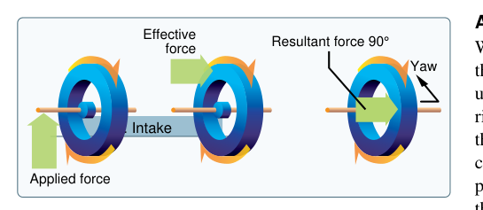
Gyroscopic precession is the second property, and it is one of the most counterintuitive phenomena in all of applied physics. When an outside force is applied to a spinning gyroscope — attempting to tilt or displace its spin axis — the gyro does not move in the direction of the applied force. Instead, it moves 90 degrees in the direction of rotation from the point where the force is applied.
A practical way to visualize this: imagine the gyro rotor as a clock face spinning counterclockwise when viewed from the front. If you press down on the 12 o'clock position, the gyro will not tilt forward at 12 o'clock. Instead, it will tilt at the 9 o'clock position — 90 degrees ahead in the direction of rotation. This 90-degree displacement of the resultant motion is the hallmark of precession.
The magnitude of precession is governed by the relationship: the greater the applied force, and the lower the angular momentum of the rotor, the greater the precession rate. Conversely, a faster or more massive rotor is more resistant to precession, exhibiting stronger rigidity. This relationship explains why gyro instrument manufacturers must carefully balance rotor speed, mass, and gimbal design to achieve the right combination of rigidity and controllable precession.
How Precession Is Used in Aviation Instruments
Precession is not merely an error to be minimized — in certain instruments, it is the working mechanism. The turn coordinator (and its predecessor, the turn-and-slip indicator) uses a gyro mounted so that precession caused by aircraft yaw is displayed as a deflection of the miniature aircraft or needle. When the aircraft enters a coordinated turn, the yawing and rolling forces precess the gyro, and the instrument displays the rate of turn. The scale is calibrated so that a standard-rate turn (3 degrees per second) produces a standardized needle or miniature aircraft deflection, allowing the pilot to execute timed turns to specific headings.
Similarly, precession plays a role in erection systems inside attitude indicators. A perfectly rigid gyro would eventually point in the wrong direction as the Earth rotates and as bearing imperfections accumulate drift. Erection systems — either pendulous vanes that use airflow, or electric torque motors — apply small, controlled, continuous forces to the gyro to precess it back to the true vertical. Because these forces are small and applied continuously, the erection is gradual and does not disturb normal instrument operation. An AMT who finds an attitude indicator with a slow or inoperative erection system will see excessive instrument errors after flight maneuvers or after the aircraft has been stored nose-high or nose-low.
Real-World Precession Errors in Flight
Two well-known gyroscopic errors affect aircraft in flight, and understanding them requires a firm grasp of precession mechanics:
- Acceleration error (magnetic compass, not gyro): While this error belongs to the magnetic compass, it is caused by a precession-like pendulous effect and is frequently tested alongside gyro principles. On the gyro instruments themselves, acceleration can temporarily displace the attitude indicator slightly, but the effect is small.
- Gyroscopic effects of the engine/propeller: The propeller itself is a large spinning gyroscope. During a pitch-up or pitch-down maneuver, propeller precession creates a yawing force on the airframe — a left-turning tendency during pitch-up in a conventional right-hand tractor propeller. AMTs must understand this when evaluating aircraft handling complaints or asymmetric wear on engine mounts.
- Gimbal error: In certain bank and pitch attitude combinations, the gimbals of a gyro instrument can align in a way that causes incorrect readings. This is more prevalent in aerobatic aircraft or during unusual attitudes and is a design limitation of the standard three-gimbal system.
- Tumbling: If an attitude indicator is operated beyond its mechanical limits (typically ±60 to ±70 degrees of pitch and up to 360 degrees of roll, depending on design), the gyro can tumble — the gimbals reach their mechanical stops and the rotor is forced into a new orientation. After tumbling, the instrument requires several minutes to re-erect before it can be trusted.
Key Numbers and Rules
- Rotor speed: Vacuum-driven gyros in light aircraft typically operate between 15,000 and 18,000 RPM; adequate vacuum is usually 4.5 to 5.5 inches of mercury (check the specific aircraft POH/AFM).
- Standard-rate turn: 3 degrees per second; a 360-degree turn completed in 2 minutes. The turn coordinator is calibrated to this rate.
- Heading indicator drift: Bearing friction and mechanical imperfection cause typical heading indicators to drift up to 3 degrees per 15 minutes under normal conditions; pilots are advised to reset to the compass every 15 minutes in cruise.
- Precession direction: Applied force results in motion 90 degrees in the direction of rotor rotation from the point of force application.
- Erection time: After power-up, a vacuum-driven attitude indicator may require 3 to 5 minutes to erect to a reliable indication; electric gyros typically erect faster.
- Tumble limits: Most light-aircraft attitude indicators are limited to approximately ±60 degrees in pitch and have full 360-degree capability in roll, but designs vary — always consult the instrument's specifications.
Common Test Traps
- Precession direction confusion: Students frequently guess that a gyro moves in the direction of the applied force. Remember: the resultant motion is always 90 degrees in the direction of rotation from the point of force application — never directly in the direction of force.
- Confusing rigidity and precession: Rigidity is the gyro's tendency to stay put; precession is the response when a force overcomes that tendency. Attitude indicators primarily use rigidity; turn coordinators primarily exploit precession.
- Vacuum system pressure values: FAA test questions may ask about normal suction gauge readings. The typical range for most light aircraft gyros is 4.5 to 5.5 in. Hg, but the aircraft's POH is the authoritative source. Low vacuum causes slow rotors, which reduces both rigidity and precession sensitivity.
- Assuming heading indicators are self-correcting: Unlike attitude indicators, most heading indicators do not have automatic magnetic north-seeking erection systems. They must be manually synchronized to the magnetic compass during straight-and-level flight. Forgetting this leads to significant navigational errors.
- Propeller precession during takeoff roll: The AMT knowledge test may present scenarios where gyroscopic precession from the propeller contributes to left-turning tendency during rotation (tail-wheel aircraft pitching up). Students must identify precession — not P-factor or torque — as the cause in those specific pitch-change scenarios.