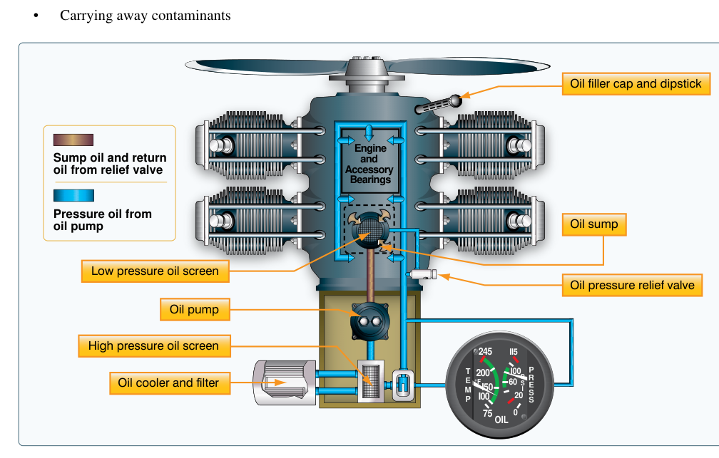
Every reciprocating aircraft engine depends on a reliable lubrication system to prevent metal-to-metal contact between moving parts, carry away heat, clean internal surfaces, and provide corrosion protection. For the majority of horizontally opposed engines used in light general aviation aircraft, the wet-sump system is the standard design. Unlike a dry-sump system — which routes oil to and from a separate external reservoir — the wet-sump design stores its entire usable oil supply in a sump cast as part of, or attached directly to, the bottom of the crankcase. This elegant simplicity reduces weight, part count, and complexity, making it perfectly suited to lower-powered engines that do not need the high oil-flow capacity demanded by large radial or turbine powerplants.
As an AMT Powerplant candidate, you will be tested on every component in this system, how oil moves through each one, what each component accomplishes, and what happens when any part fails. This article covers all of that in practical, exam-focused depth.
Where the Oil Lives: The Wet Sump
The sump is the lowest point of the engine crankcase. In a wet-sump system it acts simultaneously as the oil reservoir, the collection basin for returning oil, and the housing that partially submerges the oil pump pickup. Because the sump is integral to or directly attached to the crankcase, there is no need for external oil tank plumbing. The oil quantity is measured by a simple dipstick that threads or slides into a tube communicating directly with the sump. FAA guidance establishes that engine oil capacity and minimum safe operating levels are specified by the engine manufacturer and must be respected; operating below the minimum level risks starvation, while overfilling can cause foaming and aeration.
How the System Operates: Oil Flow Path
Understanding the complete oil circuit is the foundation of wet-sump knowledge. Oil travels in a continuous loop driven by the engine-driven oil pump.
- Pickup screen / suction strainer: A coarse mesh screen submerged in the sump catches large debris before oil enters the pump. It protects the pump gears from gross contamination.
- Oil pump: The engine-driven pump — almost always a gear-type (spur gear) pump — draws oil from the sump and pressurizes it. Two meshing gears trap oil between their teeth and the pump housing, pushing it from the inlet side to the outlet side; one gear is driven by the crankshaft or accessory gear train and the other meshes with it and is driven in turn. The pump is a positive-displacement device, meaning it pushes a fixed volume per revolution regardless of demand. Because output increases with RPM, a relief valve is mandatory.
- Pressure relief valve: Mounted at or near the pump outlet, this spring-loaded valve opens when system pressure exceeds a design limit (engine and manufacturer specific — consult the applicable engine operating limits) and bypasses excess oil back to the sump or pump inlet. This valve regulates maximum pressure; it does not maintain a fixed pressure during normal operation — it simply caps the upper limit.
- Oil filter: Pressurized oil passes through the main oil filter, which removes fine particulate contamination per the filter manufacturer's rated filtration capability. Modern engines use a full-flow spin-on filter similar in appearance to an automotive filter. The filter is equipped with a bypass valve (also called an anti-drain-back or differential pressure relief valve) that opens if the filter becomes clogged, allowing unfiltered oil to reach the engine rather than starving it entirely — a deliberate compromise of filtering in favor of continued lubrication.
- Oil cooler: On many engines, oil is routed through an air-cooled oil cooler (heat exchanger) before distribution. A thermostatic bypass valve controls whether oil flows through the cooler core or bypasses it. When oil is cold, the thermostat directs oil around the cooler to speed warm-up; as oil reaches operating temperature the thermostat progressively opens flow through the cooler core. This valve prevents overcooling and maintains oil in its optimal viscosity range.
- Distribution galleries: Oil under pressure travels through drilled passages in the crankcase and crankshaft to the main bearings, rod bearings, camshaft bearings, and (in many engines) the tappet bodies. Cylinder walls, pistons, and wrist pins are typically lubricated by splash and mist from the crankshaft throws slinging oil, or by directed squirt passages.
- Return to sump: Gravity drains oil from the cylinder heads, valve gear, and other upper-engine components back into the sump, completing the circuit.
Individual Component Details
The Gear-Type Oil Pump
The gear pump is mechanically simple and highly reliable. One gear is driven directly by the crankshaft or an accessory gear train; it meshes with and drives a second gear. As the gears unmesh on the inlet side, they create a low-pressure region that draws oil in. As they mesh on the outlet side, oil is squeezed out under pressure. There are no valves inside the pump itself; flow direction and pressure are entirely products of gear rotation. Because the pump is positive-displacement, it must have a relief valve — blocking the outlet with the engine running would destroy the pump or rupture a line.
Pressure Relief Valve
This is a simple poppet or ball-type valve held closed by a calibrated spring. When pump outlet pressure exceeds the spring's set point, the ball or poppet lifts off its seat and oil recirculates. The correct spring tension (and therefore the system's maximum operating pressure) is set at overhaul. An improperly adjusted or stuck-closed relief valve can cause dangerously high oil pressure; a stuck-open valve results in chronically low pressure and inadequate lubrication.
Oil Filter and Bypass Valve
The full-flow filter traps particles according to its manufacturer-rated filtration capability during normal operation. At each oil change, the technician inspects the used filter element for metal particles — a quick, practical indicator of internal engine wear. If ferrous metal flakes or shavings are found, further investigation is required before returning the engine to service. The bypass valve opens when the pressure differential across a clogged filter reaches a specified value set by the filter manufacturer for that design. Remember: a bypass valve opening means the engine is receiving unfiltered oil — far better than no oil, but a maintenance alert condition.
Oil Temperature and Pressure Gauges
The cockpit oil pressure gauge receives its reading from a pressure transducer or mechanical sensing line tapped into the pressurized distribution system, typically between the filter outlet and the main gallery. The oil temperature gauge sensor is usually located at the oil inlet to the engine (after the cooler) or in the sump. Both indications are mandatory for engine monitoring. Low oil pressure on takeoff is an immediate abort/emergency condition; high oil temperature with normal pressure may indicate cooler malfunction or reduced oil quantity.
Why Wet-Sump Design Matters
The simplicity of the wet-sump system is both its primary advantage and its key limitation. With no external tank and minimal plumbing, there are fewer potential leak points, less maintenance complexity, and reduced weight — all valuable in a light aircraft. However, the design is susceptible to oil starvation in prolonged unusual attitudes (such as extended inverted flight or steep sustained climbs/dives) because the pickup tube can be uncovered when the oil migrates away from the sump. This is why most light trainers are not approved for sustained inverted flight; aerobatic aircraft certified for such maneuvers typically use dry-sump systems.
Another practical concern is oil dilution and contamination. Because the sump is integral to the crankcase, any fuel that leaks past worn piston rings or any water from condensation collects in the same reservoir as the oil. Regular oil analysis and adherence to oil change intervals are critical maintenance practices.
Key Numbers and Rules
- Oil pressure normal range: Engine-specific — always consult the applicable engine manufacturer's operating limits (POH/engine manual); idle minimums and cruise operating pressures differ and should not be treated as a single generic range. Minimum and maximum red-line limits vary by engine.
- Oil temperature normal range: Engine-specific; consult the manufacturer's TCDS/operating limitations for the applicable minimum, normal cruise, and maximum (redline) values. Oil must reach normal operating temperature before high power operation to ensure proper viscosity.
- Filter bypass valve differential: Opens at a pressure differential specified by the filter/engine manufacturer for that design — exact value is engine/filter specific.
- Oil change intervals: Typically every 25–50 hours or per calendar interval per the engine manufacturer's instructions — not a universal FAA-mandated number, but a manufacturer requirement that is legally binding under 14 CFR Part 43 / maintenance manuals.
- Dipstick check: Always check oil with the aircraft on level ground and the engine shutdown for the time interval specified in the POH to allow oil to drain back to the sump.
- Contaminated filter contents: Finding metallic particles in the filter is cause for grounding the aircraft and investigating the source before further flight.
Memory Aid
To recall the order of components in the oil flow path, use the phrase "Pick up Pressure, Filter the Flow, Cool it Down, Distribute Around":
- Pick up — Pickup screen at the sump
- Pressure — Gear pump builds pressure; relief valve limits it
- Filter — Full-flow oil filter removes contaminants
- Flow (Cool it Down) — Thermostatic oil cooler controls temperature
- Distribute Around — Pressurized galleries deliver oil to all bearings
Common Test Traps
- Relief valve vs. bypass valve confusion: The pressure relief valve limits maximum pump output pressure and is near the pump. The filter bypass valve opens when the filter is clogged. They are two separate valves with two different jobs — test questions often describe one and ask you to identify the other.
- Wet sump vs. dry sump: A wet-sump engine has no separate external oil tank — the sump IS the reservoir. A dry-sump system has an external tank and scavenge pumps. Confusing the two is a common error.
- Low oil pressure causes: The FAA tests whether students understand that low oil pressure can result from low oil quantity, a worn or failed pump, an improperly adjusted or stuck-open relief valve, a clogged pickup screen, or excessively thin (low-viscosity) oil — not just low oil level.
- High oil temperature with normal pressure: This scenario often indicates a malfunctioning oil cooler thermostat stuck in the bypass position, reduced oil quantity (less oil circulating absorbs more heat), or a blocked cooler. It does not automatically mean a failing pump.
- Filter bypass valve opening is NOT normal operation: Some students believe the bypass valve routinely cycles open. It should not open during normal operation; its opening signals a clogged filter requiring immediate maintenance attention.