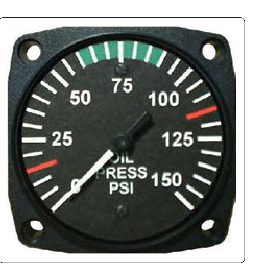
Engine lubrication is the lifeblood of any reciprocating or turbine aircraft powerplant. Oil performs four critical jobs simultaneously: it lubricates moving parts to reduce friction and wear, cools internal components that cannot be reached by the engine's cooling airflow, cleans the engine by suspending contaminants and carrying them to the filter, and seals clearances between pistons, rings, and cylinder walls. For the aviation maintenance technician (AMT) and the pilots who rely on their work, the two most telling indicators of lubrication system health are oil temperature and oil pressure. Knowing what normal looks like — and, critically, what abnormal readings indicate — is essential for preventing catastrophic engine failure in flight.
This article covers the operating principles behind oil temperature and pressure gauges, the acceptable ranges specified by engine manufacturers and referenced in FAA guidance, and a systematic troubleshooting approach for common abnormal indications. All information is grounded in FAA-H-8083-32 (Aviation Maintenance Technician Handbook — Powerplant) and supporting FAA publications.
How Oil Pressure and Temperature Are Generated and Measured
In a typical reciprocating engine, an engine-driven oil pump — usually a gear-type pump — draws oil from the sump or a remote reservoir and forces it through galleries and passages to the bearings, camshaft lobes, rocker arms, and other critical surfaces. The pressure developed by this pump is the oil pressure indicated in the cockpit. A pressure relief valve is installed in the system to bypass excess oil back to the inlet side of the pump whenever pressure exceeds the design limit, preventing damage to seals and gaskets at high power settings or when cold, thick oil first enters the system.
Oil temperature is measured most commonly with an electrical resistance-type or thermocouple sensor placed at a strategic point in the oil circuit. On most reciprocating engines, the temperature sender is located at the oil inlet to the engine (measuring oil coming from the cooler and reservoir) or at the oil outlet (measuring oil leaving the engine after absorbing heat). The specific sensor location matters when interpreting readings: an inlet temperature sensor will read lower than an outlet sensor under the same operating conditions. Manufacturers specify which location their gauge references, so always consult the engine type certificate data sheet or overhaul manual.
In turbine (gas turbine) engines, the lubrication system operates on the same principles but at higher temperatures and with different oil formulations (typically synthetic oils meeting MIL-PRF-23699, such as Type II/HTS, or MIL-PRF-7808 Type I). Oil pressure and temperature are still the primary health indicators, and the same logic — low pressure is dangerous, high temperature signals stress — applies.
Acceptable Operating Ranges
Every engine has an FAA-approved operating range established during type certification. These ranges are published in the engine manufacturer's operator's manual, the aircraft's Pilot's Operating Handbook (POH), and on the instrument face itself, which is color-coded by regulation. Understanding the color arc system is fundamental:
- Green arc: The normal operating range. Both oil pressure and oil temperature gauges should read in the green arc during steady cruise flight after the engine has warmed up.
- Yellow arc: A caution range. Operation in this range is permitted for limited time or under specific conditions, but the technician or pilot should monitor closely and investigate the cause. On oil temperature gauges, the yellow arc typically appears at both the low end (cold oil, before warmup) and the high end (approaching maximum limits).
- Red line: A maximum or minimum limit. Sustained operation beyond a red line is prohibited and may indicate impending system failure. A red line on the low end of an oil pressure gauge represents the minimum permissible pressure; crossing it warrants immediate action.
While specific numbers vary by engine model, many small reciprocating aircraft engines are commonly specified with a minimum idle oil pressure of around 25 psi, cruise pressures in roughly the 25 to 60 psi range, and a maximum not to exceed approximately 90 to 100 psi. Oil temperatures at cruise typically fall in a normal operating range of approximately 100°F to 245°F, with maximum (redline) limits often around 245°F to 250°F. Always defer to the specific engine's data sheet — these representative values are guidelines, not universal specifications.
It is worth noting that oil pressure is often observed to run high during cold starts, because cold oil is more viscous and harder to pump through tight clearances. The relief valve may open, but pressure may still read above the green arc momentarily on some engines, though other engines' relief valves are designed to keep pressure within the green arc even when the oil is cold, so this behavior is engine-dependent rather than universal. When it does occur, it is normal and should fall into the green arc as oil warms. Prolonged operation with cold, thick oil at high pressure — especially at high power settings — can damage seals, so a proper engine warm-up at reduced power is both good practice and manufacturer-required procedure on many engines.
Why Oil Monitoring Matters for Safety
The consequences of undetected lubrication failure are severe and swift. A reciprocating engine bearing operating without adequate oil film will generate friction heat that quickly exceeds the melting point of the bearing material. Connecting rod bearings are especially vulnerable; a spun or seized connecting rod bearing can result in the rod punching through the crankcase — a catastrophic failure with zero warning time and typically no recovery in flight. Turbine engine bearing failures caused by oil starvation are similarly catastrophic and can result in uncontained engine failure.
Beyond catastrophic failure, gradual lubrication degradation causes accelerated wear that shortens Time Between Overhaul (TBO) and increases the likelihood of finding metal particles in the oil filter — a sign that internal damage is already progressing. The FAA emphasizes oil analysis as a valuable trend-monitoring tool: spectrographic oil analysis programs (SOAP) can detect elevated levels of aluminum, iron, copper, and other metals that correspond to specific internal components, alerting technicians to developing problems before they cause failure.
Troubleshooting Abnormal Oil Pressure Readings
When oil pressure is outside the normal range, a systematic approach will isolate the cause efficiently.
Low Oil Pressure
Low oil pressure is always treated as an emergency in flight and an urgent maintenance concern on the ground. Possible causes include:
- Low oil quantity: The most common cause. Check oil level immediately. Consumption above one quart per hour on most engines is considered excessive and warrants investigation.
- Worn or damaged oil pump: Internal gear wear reduces pump efficiency and output pressure, particularly at idle speeds.
- Clogged oil suction screen or inlet strainer: Restricts oil flow before it reaches the pump. Check and clean suction screens at each oil change.
- Faulty pressure relief valve: A relief valve stuck open bypasses oil continuously, dropping system pressure. Remove, inspect, and test the valve spring and seat.
- Worn main or rod bearings: Excessive clearance allows oil to escape the bearing faster than the pump can maintain pressure, especially at low RPM. This is a serious internal engine finding.
- Defective pressure gauge or sender: A false low reading is possible. Cross-check with a calibrated external gauge before condemning the engine.
High Oil Pressure
High oil pressure most commonly occurs during cold starts with viscous oil or indicates a blocked oil gallery restricting flow downstream of the pump. Additional causes include a relief valve stuck closed or a spring that is too stiff (perhaps from incorrect maintenance reassembly). Persistent high pressure in a warm engine warrants immediate investigation to prevent seal damage.
Troubleshooting Abnormal Oil Temperature Readings
High oil temperature may indicate:
- Blocked or bypassed oil cooler: Inspect the cooler for external fin blockage (insects, debris) and ensure the thermostatic bypass valve is operating correctly. A bypass valve stuck open routes oil around the cooler at all times, preventing heat dissipation.
- Low oil quantity: Less oil cycling through the system means each volume of oil spends longer absorbing heat before it returns to the sump, raising average temperature.
- Prolonged high-power operation: Extended climb at high power without adequate airspeed (reducing cooling airflow) can push temperatures into the yellow arc. This is an operational issue but may also reveal marginal cooler capacity.
- Detonation or pre-ignition: Abnormal combustion raises in-cylinder temperatures dramatically, overheating the oil that cools the pistons from beneath. High oil temperature accompanied by rough running should immediately raise suspicion of detonation.
Low oil temperature — a reading that stays persistently in the low yellow arc even after adequate warm-up — typically indicates a thermostatic bypass valve stuck open, causing oil to continuously bypass the cooler before it can warm up, or a defective temperature sender.
Key Numbers and Rules
- Green arc = normal: Both gauges must read in the green during cruise; anything else requires investigation.
- Oil pressure red-line minimum: Varies by engine, but typically around 10–25 psi at idle; land as soon as practicable if pressure drops below minimum.
- Cold start high pressure: Commonly seen and expected on many engines; should stabilize within the green arc after warm-up (usually within 30 seconds to 2 minutes at reduced power), though behavior varies by engine and relief valve design.
- Oil temperature maximum: Commonly around 245°F–250°F for air-cooled reciprocating engines; consult the specific engine manual.
- Oil consumption: Rates exceeding approximately one quart per hour are generally considered excessive for most reciprocating engines, though engine-specific limits apply.
- Filter inspection: At every oil change, cut open or inspect the filter for metallic particles — a critical maintenance step that can reveal internal wear before instrument indications appear.
Common Test Traps
- Confusing the sensor location: Knowing whether the temperature sensor is at the oil inlet or outlet changes how you interpret a reading. Some exam questions specify sensor location — read carefully.
- Assuming high pressure is always bad: High pressure on a cold start is common and often normal, though it depends on the specific engine's relief valve design. High pressure in a fully-warmed engine is a concern. Context — oil temperature — determines whether high pressure is normal or a defect.
- Overlooking the gauge or sender as the problem: Before condemning a pump or engine, always verify the gauge and sender with a known-good external instrument. Faulty senders are a common cause of false abnormal readings.
- Forgetting that low quantity causes both low pressure AND high temperature: These two abnormal indications occurring together should immediately raise the suspicion of insufficient oil quantity, not two separate unrelated failures.
- Mixing up the relief valve failure modes: A relief valve stuck OPEN causes low pressure (oil bypasses back to inlet). A relief valve stuck CLOSED causes abnormally high pressure. Students frequently reverse these on exams.