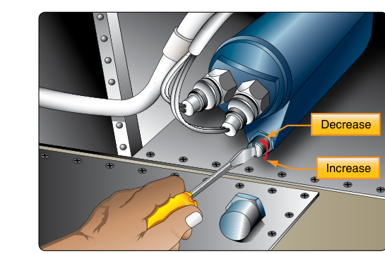
Every reciprocating aircraft engine depends on a steady, properly pressurized supply of oil to keep bearings, gears, and cylinder walls from destroying themselves within minutes of start-up. Yet too much pressure is just as dangerous as too little — it can blow oil seals, rupture gaskets, and starve downstream passages by forcing the pump outlet into bypass. The oil pressure relief valve is the mechanical guardian that balances these extremes, ensuring the engine always sees oil pressure within its design limits regardless of oil viscosity, temperature, or engine speed. For the AMT powerplant candidate, mastering how this valve works, why it is adjusted, and how to set it correctly is both a practical necessity and a frequent test topic.
Role of the Relief Valve in the Lubrication System
A typical aircraft engine uses a positive-displacement gear-type oil pump driven directly from the engine's accessory section. Because a gear pump moves a fixed volume of oil with every revolution, output pressure rises sharply with engine RPM and with cold, thick oil. Without a relief valve, system pressure at high RPM or during a cold start could rise well beyond the engine's normal operating limit, damaging seals and fittings.
The oil pressure relief valve — sometimes called the pressure-regulating valve — solves this by providing a calibrated bypass path. It is typically located in or very near the pump body, between the pump outlet and the main oil gallery. When pressure reaches the valve's set point, the valve opens and routes excess oil back to the pump inlet or directly to the sump. The pump continues working at full displacement, but now a portion of its output simply recirculates rather than pressurizing the system beyond the limit. The result is a near-constant delivery pressure to the engine regardless of how hard the pump is working.
How the Relief Valve Works
Basic Construction
Most aircraft engine oil pressure relief valves are spring-loaded ball or plunger valves. A hardened steel ball or cylindrical plunger is held against a machined seat by a calibrated coil spring. Pump outlet pressure acts on the upstream face of the ball or plunger. As long as that pressure stays below the spring's preload force, the valve remains closed and all pump output flows to the engine. When pressure rises to the set point, it overcomes the spring, lifts the ball or plunger off its seat, and oil escapes through the bypass port back to the inlet side of the pump or to the sump.
The Pressure Relationship
The cracking pressure — the precise pressure at which the valve first begins to open — is determined entirely by spring preload. A stiffer spring or one that is compressed to a shorter free length produces a higher cracking pressure. A weaker or more extended spring produces a lower one. This is the fundamental principle behind adjustment: technicians change preload to move the cracking pressure up or down.
It is important to understand that the relief valve does not regulate pressure at a precise single value the way an electronic pressure regulator might. Instead, it limits the maximum pressure. At low RPM or with warm, thin oil the pump may not generate enough pressure to crack the valve at all — in that case the valve stays closed and full pump output goes to the engine. This is normal; the relief valve only becomes active when the pump would otherwise exceed the limit.
Why Correct Oil Pressure Matters
Oil pressure is directly linked to the oil film thickness maintained at every bearing surface. Too low, and the hydrodynamic film breaks down, allowing metal-to-metal contact, rapid wear, and catastrophic bearing failure. Too high, and the force required to pump oil through narrow passages increases, oil seals deform or blow out, and the constant bypass of oil back to the sump can overheat the oil supply. FAA guidance in the Aviation Maintenance Handbook (FAA-H-8083-32) makes clear that maintaining oil pressure within the engine manufacturer's specified range is one of the primary responsibilities of the powerplant technician.
Normal operating oil pressure for reciprocating aircraft engines varies by make and model, and the specific limits must always be verified against the engine manufacturer's overhaul manual rather than a fixed generic figure. FAA-H-8083-32 emphasizes checking published limits for the specific engine being serviced, since minimum idle pressures and maximum operating pressures differ considerably between engine types.
Adjustment Procedure
Tools and Preparation
Before adjusting any oil pressure relief valve, the technician must confirm that low or high oil pressure is actually caused by the relief valve and not by another factor such as a worn pump, blocked oil passages, incorrect oil viscosity, or a faulty pressure gauge or sending unit. Troubleshooting oil pressure discrepancies always begins with verifying that the gauge and transducer are reading correctly and that oil quantity and viscosity are appropriate for the ambient temperature conditions.
A calibrated master oil pressure gauge should be used to cross-check the cockpit instrument before touching the relief valve. Only once the instrument is confirmed accurate and all other causes are ruled out should adjustment begin.
Making the Adjustment
The adjustment mechanism varies by engine design but most commonly consists of one of the following:
- Adjusting screw with lock nut: A threaded screw bears directly on the top of the spring. Turning the screw inward (clockwise) compresses the spring, raising the cracking pressure and thus increasing system oil pressure. Turning it outward (counterclockwise) relaxes spring preload, lowering pressure. A jam nut locks the screw in the selected position.
- Shim adjustment: Some designs use shims stacked beneath the spring to control its preload. Adding shims increases spring compression and raises pressure; removing shims lowers pressure.
Adjustments should always be made in small increments. After each adjustment, the engine must be run to normal operating temperature and the pressure rechecked. Oil viscosity changes dramatically with temperature, and pressure readings taken on a cold engine are not representative of stabilized normal-operation values. The FAA recommends checking pressure only after the engine has reached its normal operating oil temperature range.
Once the correct pressure is achieved, the lock nut must be torqued to the manufacturer's specification and safety-wired if called for. The oil system should then be inspected for any leaks at the valve and adjacent fittings before returning the aircraft to service.
Key Numbers and Rules
- Relief valves are spring-loaded ball or plunger designs that open when pump outlet pressure exceeds the spring's set force.
- Turning the adjustment screw in (clockwise) increases oil pressure; turning it out (counterclockwise) decreases oil pressure.
- Adding shims increases spring preload and raises cracking pressure.
- Always verify the oil pressure gauge accuracy with a calibrated master gauge before adjusting the relief valve.
- Always check and record adjusted pressure with oil at normal operating temperature, not cold.
- Refer to the specific engine manufacturer's overhaul or maintenance manual for exact pressure limits — no universal value applies to all engines.
- After adjustment, lock the screw with the jam nut, apply safety wire per the manufacturer's instructions, and inspect for leaks before return to service.
Common Test Traps
- Confusing direction of adjustment: A very common knowledge test question asks what happens when the relief valve screw is turned in. Many candidates confuse this — turning in compresses the spring, which increases pressure. Think of it as tightening a vise on the spring.
- Assuming the relief valve controls minimum pressure: The relief valve only limits maximum pressure. Low oil pressure at idle or warm operating conditions is not corrected by tightening the relief valve — the pump or bearings must be investigated instead.
- Skipping gauge verification: Adjusting the valve before verifying gauge accuracy is a fundamental error. The test often presents scenarios where the gauge is faulty; the correct first action is always to cross-check with a master gauge.
- Checking pressure before oil is warm: Cold, viscous oil produces unrepresentative pressure readings, typically higher than what the engine will show once oil reaches normal operating temperature. Adjustments made on a cold engine can result in incorrect pressure once the oil warms and thins out, so the system must always be checked and adjusted at stabilized operating temperature.
- Confusing the relief valve with the bypass valve: The oil filter bypass valve is a separate component that opens to route unfiltered oil around a clogged filter, protecting the engine from oil starvation. It does not regulate system pressure and is not adjustable in the same way as the pressure relief valve.
Mastering the oil pressure relief valve — its design, its role in the lubrication circuit, and the correct adjustment technique — gives powerplant technicians a direct tool to protect engines from one of aviation's most common sources of in-flight emergencies. The knowledge is equally valuable in the hangar and on the FAA written examination.