Every reciprocating and turbine aircraft engine depends on a continuous, pressurized supply of oil to keep bearing surfaces separated, carry away heat, and flush out contaminants. The oil pump is the heart of that system — a positive-displacement device that moves a fixed volume of oil with each revolution regardless of the downstream resistance. Three pump designs appear repeatedly in aircraft engine lubrication systems: the gear pump, the gerotor pump, and the vane pump. Each accomplishes the same fundamental job through different mechanical means, and the FAA Powerplant written knowledge test expects you to understand not only how they work but why engineers choose one over another and how each can fail.
This article walks through the operating principles, construction details, advantages, limitations, and maintenance considerations of all three types, grounded in the FAA Aviation Maintenance Handbook — Powerplant (FAA-H-8083-32) and the related General handbook (FAA-H-8083-30).
Positive Displacement: The Shared Foundation
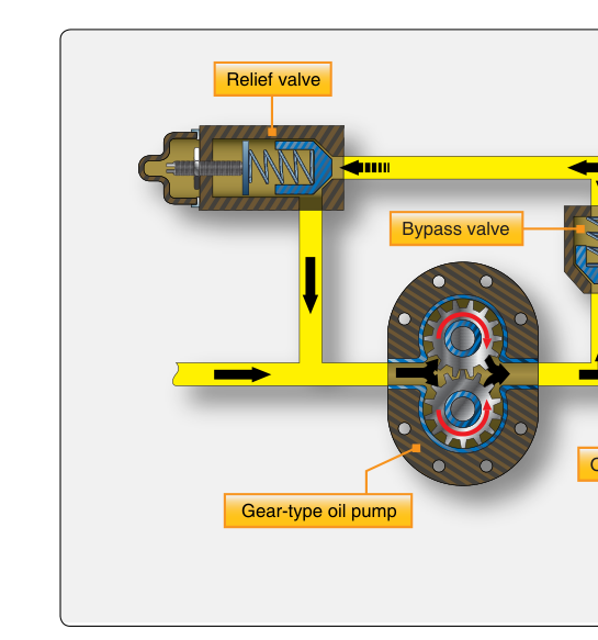
Before examining individual types, it is worth understanding what positive displacement means in practice. Unlike a centrifugal pump, which relies on spinning oil at high velocity and converting kinetic energy to pressure, a positive-displacement pump traps a defined pocket of fluid on the inlet side, carries it mechanically around to the outlet side, and forces it into the pressure line. The result is a flow rate that is nearly proportional to pump speed, and a pressure that is determined entirely by system resistance — not by the pump itself. This is why every aircraft oil system requires a pressure-relief valve: without one, a positive-displacement pump running against a blocked outlet would build pressure until something breaks.
Gear Pumps
The gear pump is the simplest, most common, and most rugged oil pump type used in aircraft engines. It consists of two meshing spur gears — a drive gear connected to the engine and an idler gear — both enclosed in a tight-fitting housing. As the gears rotate, the spaces between the gear teeth on the inlet side expand, drawing oil in from the sump or tank. The teeth carry pockets of oil around the outside of each gear (between the gear teeth and the housing wall) toward the outlet. When the teeth mesh again on the outlet side, the space between them decreases, squeezing oil out into the pressure line. Crucially, oil cannot flow back through the mesh point because the teeth are always in contact there, which is what makes the design positive-displacement.
Gear pumps are valued for their simplicity and reliability. They have very few moving parts — essentially just the two gears and the housing — making them easy to inspect and overhaul. They tolerate the contaminated or degraded oil that sometimes exists during cold starts better than more precisely-fitted designs. The close tolerances between the gear faces and the housing end plates are the main wear surfaces; as these clearances increase with use, internal leakage (called slip) increases and pump output efficiency drops. During overhaul, technicians measure gear end clearance and gear-to-housing backlash and compare them to manufacturer limits to determine serviceability.
Gear-type pumps (including gerotor pumps) are widely used in aircraft reciprocating engines for both the pressure pump (sending oil to bearings) and the scavenge pumps (returning oil from the engine back to the tank). Because scavenge pumps must handle oil that is foamy and mixed with blow-by gases, their capacity is greater than that of the pressure pump — scavenge pumps are intentionally over-sized to prevent oil from pooling in the engine.
Gerotor Pumps
The gerotor (short for generated rotor) pump is a variation on the internal-gear concept and is used extensively in modern aircraft engines, particularly flat-opposed engines and many turbine accessory gearboxes. A gerotor pump has two rotating elements: an inner rotor with external lobes and an outer rotor (sometimes called the ring gear) with one more internal lobe than the inner rotor has external lobes. The inner rotor is driven by the engine; its off-center mounting causes the outer rotor to rotate at a slightly different speed.
As the two rotors turn together, the space between each pair of adjacent lobes changes continuously. On the intake side of the pump housing, the chambers expand and draw oil in. On the discharge side, the chambers shrink and force oil out under pressure. The kidney-shaped inlet and outlet ports in the end plate align with the expanding and contracting chambers at precisely the right moments. Because both rotors are always in contact around their full circumference, there is no direct internal leak path between inlet and outlet — the design is inherently efficient and quiet.
Gerotor pumps offer high volumetric efficiency in a compact, low-profile package. Because there are no external gear teeth to machine to fine tolerances, manufacturing is relatively straightforward, and the smooth lobe profile reduces pressure pulsations compared to spur-gear pumps. The primary disadvantage is sensitivity to debris: the precise fit of the lobes means that hard particles can score the rotor faces or the housing bore more readily than in a heavier-duty gear pump. This makes pre-oiling, clean oil, and proper filtration especially important on gerotor-equipped engines.
Vane Pumps
The vane pump uses a cylindrical rotor mounted eccentrically inside a circular cam ring. Slots cut radially into the rotor hold flat rectangular vanes that slide freely in and out. As the rotor spins, centrifugal force (and sometimes light springs) pushes the vanes outward against the cam ring wall. Because the rotor is offset from the center of the cam ring, the space between adjacent vanes grows on the inlet arc and shrinks on the outlet arc, trapping and then expelling oil with each revolution.
Vane pumps can achieve very smooth, nearly pulse-free flow because multiple vanes are always bridging the inlet-to-outlet transition simultaneously. They are also self-compensating to a degree: as vanes wear, centrifugal force continues pressing them against the cam ring, maintaining a reasonable seal longer than gear or gerotor pumps maintain theirs. However, vane pumps are more mechanically complex, and the vanes themselves are a wear item that must be inspected and replaced at overhaul. High-viscosity cold oil can overload the vanes during cold starts if they must overcome stiff spring resistance. Vane pumps appear more commonly in hydraulic systems and some fuel boost pump applications, but they do see use in engine lubrication on certain engine designs and in some dry-sump scavenge applications.
Why It Matters: Safety and Maintenance Implications
Oil pump failure or degraded output is one of the fastest paths to catastrophic engine failure in flight. A gear pump with worn end clearances may provide adequate pressure at cruise power but fail to maintain minimum pressure during low-RPM taxi or descent. A gerotor pump can suffer sudden output loss if a broken lobe from internal damage circulates through the system. Understanding these failure modes tells an AMT where to look: check pump clearances on the bench, inspect the pressure relief valve for sticking (a stuck-open relief valve mimics pump failure), and examine the oil filter element for metallic particles that indicate internal pump wear.
Pressure pumps and scavenge pumps on dry-sump engines are often driven from the same accessory drive pad or gear train. If a scavenge pump fails and oil accumulates in the engine, it can be ingested by the crankcase breather system, consumed during combustion, or — in inverted-flight applications — starve the pressure pump of oil from the tank.
Key Numbers and Rules
- Scavenge pump capacity: scavenge pumps are intentionally sized with greater capacity than the pressure pump to prevent oil accumulation in sumps and bearing cavities; the handbook does not specify a universal numeric oversizing percentage, as actual sizing is engine-specific.
- Pressure relief valve: required on all positive-displacement oil pumps; set to bypass excess oil back to the inlet or tank when system pressure exceeds a design limit (specific values vary by engine model — always consult the manufacturer's overhaul manual).
- End clearance limits: gear and gerotor pump end clearances are measured with a feeler gauge; the handbook does not give a universal numeric tolerance — worn clearances beyond the manufacturer's specified service limit (found in the applicable overhaul manual) are cause for pump replacement or reconditioning.
- Drive mechanism: oil pumps are engine-driven accessories — they produce zero flow when the engine is not running, which is why external pre-oilers are used during engine storage and return-to-service procedures.
- Contamination sensitivity: gerotor pumps are generally more sensitive to particle contamination than spur-gear pumps due to tighter lobe-to-housing clearances.
Common Test Traps
- Confusing pump type with application: the FAA test may ask which pump type is most common in aircraft reciprocating engine lubrication systems — gear (including gerotor) pumps are the answer; vane pumps are less common in lubrication but more common in hydraulic systems.
- Forgetting the relief valve requirement: students sometimes state that the pump controls system oil pressure — it does not. The pressure relief valve controls maximum pressure; the pump simply supplies flow.
- Scavenge vs. pressure pump sizing: a common distractor suggests the pressure pump should be larger; in reality, the scavenge pump must be larger to ensure oil does not accumulate inside the engine.
- Vane wear compensation: the test may describe a pump that maintains output as vanes wear and ask which type it is — the vane pump's centrifugal self-seating action is the correct answer, not the gear pump.
- Gerotor rotor count: remember that the outer rotor always has exactly one more lobe than the inner rotor — this geometry is what creates the expanding and contracting chambers that move oil.