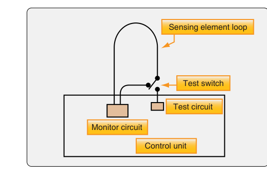
Engine fire detection is one of the most safety-critical systems on any aircraft powered by a turbine or reciprocating engine. When a fire breaks out in an engine nacelle, wheel well, or baggage compartment, a fast, reliable warning gives the crew time to execute emergency procedures before structural damage or catastrophic failure occurs. Aircraft mechanics must understand not only how each detection system works, but also why a particular design was chosen for a given aircraft and how failures manifest during maintenance. The FAA groups fire detection systems into several fundamental categories: thermal switch systems, thermocouple systems, and continuous-loop systems. Each operates on a distinct physical principle, and each has characteristic strengths and failure modes that appear on the AMT Powerplant knowledge test.
Why Fire Detection Matters
An undetected engine fire can burn through control cables, fuel and hydraulic lines, and structural members in seconds. Early detection allows the flight crew to shut down the affected engine, deploy fire-suppression agents, and divert to the nearest suitable airport. For mechanics, understanding detection systems is equally important on the ground: an improperly installed detector, a chafed wire, or a contaminated sensing element can produce nuisance warnings that erode crew confidence, or—worse—fail to warn when a real fire exists. 14 CFR Part 33 addresses turbine engine design and fire zone containment, while the requirement for a fire detection system on the type-certificated aircraft itself is found in 14 CFR 25.1203 (transport category) or 14 CFR 23.1203 (normal category), as applicable.
Thermal Switch Systems
The thermal switch (also called a spot detector) is the simplest and oldest type of fire detector. It consists of a bimetallic thermostat switch mounted at one or more specific locations in the fire zone—typically near components most likely to ignite, such as the turbine exhaust section or near the engine accessories. The switch contains two metals bonded together that expand at different rates when heated. Below the alarm threshold, the switch contact is open. When temperature rises to the alarm set point (typically around 250 °F to 300 °F for many installations, though the exact value depends on the aircraft type-certificate data), the bimetallic element distorts, closes the circuit, and completes the electrical path to the cockpit warning light and/or bell.
Most thermal switch circuits use multiple detectors wired in parallel. If any single detector reaches the alarm temperature, it closes and activates the warning. A test circuit is also built in—a test switch momentarily applies current through a small heater coil on each detector to verify that the circuit is intact and that each switch can close properly. Because only a single point in the fire zone is sampled, thermal switch systems can miss a slowly developing fire that stays below the alarm temperature or one that occurs between the detector locations. Thermal switches are most common on light general-aviation aircraft and older designs where simplicity and low weight are paramount.
Thermocouple Systems
Thermocouple fire detection relies on a completely different physical principle: the Seebeck effect. When two dissimilar metals are joined at two junctions and one junction is at a higher temperature than the other, a small voltage is generated proportional to the temperature difference between the junctions. This is the key distinction from thermal switch systems—a thermocouple detector responds to the rate of temperature rise, not to an absolute temperature value.
In a typical aircraft thermocouple fire-detection circuit, one junction (called the hot junction or detector junction) is located in the fire zone, while the other (the cold junction or reference junction) is shielded from the fire zone and remains at ambient temperature. A sensitive relay in the control unit monitors the voltage output. Under normal engine heating conditions, temperature rises gradually and both junctions warm at nearly the same rate, producing little net voltage. If a fire breaks out, the hot junction heats rapidly while the cold junction stays cool, generating enough voltage to energize the relay and illuminate the fire warning light.
The rate-of-rise characteristic is both an advantage and a limitation. It means the system will not alarm during a slow engine warm-up—preventing nuisance alerts—but it also means that a smoldering fire that heats the fire zone very slowly may not trip the alarm as quickly as an explosive fire would. Thermocouple systems are not normally provided with a test circuit that can actually verify the sensing element, so maintenance testing typically involves applying a heat gun to the detector junctions and confirming cockpit annunciation. These systems are found on many older turbine-powered transport and military aircraft.
Continuous-Loop Systems
Continuous-loop detectors are the dominant technology on modern turbine-powered commercial and business aircraft. Instead of sampling temperature at one or a few points, a continuous-loop sensor covers an entire zone with a single sensing element that runs along the entire perimeter of the fire zone—hence the name. Two major designs are common: the Kidde system and the Fenwal system (often called the pneumatic or gas-pressure type).
Kidde (Electrical Resistance) Continuous Loop
The Kidde design uses a stainless-steel outer tube surrounding a central conductor, with a thermistor-type material (a ceramic core with semiconductor properties) filling the space between them. At ambient temperature the material has high electrical resistance, so virtually no current flows. As temperature rises, the resistance of the semiconductor core decreases, allowing more current to flow. When resistance drops below a threshold value—indicating fire-level heat—the control unit detects the increased current and triggers the warning. A separate wire monitors continuity so that a broken loop produces a fault indication rather than a false fire warning, which is an important safety feature. The system can also be designed with dual loops for redundancy: two loops run in parallel, and both must agree before a fire alarm sounds (fault-tolerant design), or either loop alone is sufficient depending on the aircraft design.
Fenwal (Pneumatic or Gas-Pressure) Continuous Loop
The Fenwal system uses a single sensing element consisting of an Inconel outer tube surrounding a hydrogen-charged core packed with a eutectic salt responder material. There are two responding mechanisms along this one sensing element: (1) as average temperature along the loop rises, the hydrogen gas in the core expands, raising internal pressure and closing a pressure switch to trigger the alarm; and (2) if a localized hot spot exceeds a higher threshold temperature, the eutectic salt at that point loses its ability to insulate, allowing the inner conductor to contact the outer tube wall and close the alarm circuit directly, giving faster local detection. This dual response—average temperature rise along the full loop and localized hot-spot detection—makes the Fenwal system extremely reliable and gives it both rate-of-rise and absolute-temperature response characteristics. Like the Kidde system, the Fenwal loop can detect a break in the sensing element and will generate a fault annunciation rather than a spurious fire warning.
Key Numbers and Rules
- Thermal switch: bimetallic spot detectors wired in parallel; closure of any single switch triggers the alarm; tests by energizing a heater coil in each detector.
- Thermocouple: responds to rate of temperature rise, not absolute temperature; will not false-alarm during normal engine warm-up; cold and hot junctions must be at different temperatures to generate output.
- Continuous loop (Kidde): resistance of core material decreases with increasing temperature; increased current flow triggers the warning unit; a broken loop gives a fault light, not a fire light.
- Continuous loop (Fenwal): pneumatic/gas-pressure design; provides both average-overheat and localized hot-spot detection; dual-response mechanism; broken element gives fault indication.
- All certified fire detection systems must be able to be tested from the cockpit without simulating an actual fire, per airworthiness requirements.
- A fire detection system fault or loop fault annunciation means the sensing loop is broken or has an open circuit—not that there is a fire.
Common Test Traps
- Thermocouple responds to rate of rise, not absolute temperature. Test questions often describe a scenario where the fire zone heats slowly—a thermocouple system may not alarm promptly, while a thermal switch set to an absolute temperature would. Know this distinction cold.
- Parallel vs. series wiring of thermal switches. Thermal switch detectors are wired in parallel—any one switch closing completes the circuit. Students sometimes assume series wiring (where all switches must close), which is incorrect.
- Broken continuous loop = fault, not fire. A common distractor is to say that an open circuit in a Kidde or Fenwal loop produces a fire warning. It produces a fault warning. Only increased current flow (Kidde) or pressure rise (Fenwal) produces a fire warning.
- Thermocouple test circuits. Unlike thermal switch systems that have built-in heater test circuits, thermocouple systems are typically tested by applying external heat to the junctions. Confusing which system has which test method is a frequent error.
- Kidde vs. Fenwal operating principle. Both are continuous-loop systems, but one is electrical-resistance based and the other is pneumatic/gas-pressure based. The exam may describe operating characteristics and ask you to identify the system type—know that decreasing resistance triggering increased current points to Kidde, while gas pressure rise points to Fenwal.