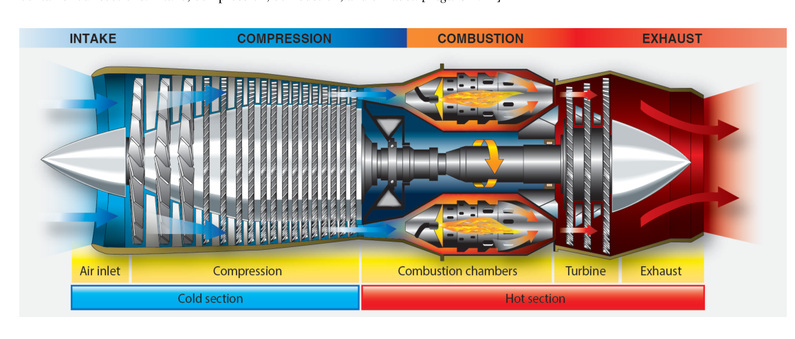
Turbine engines operate at rotational speeds, temperatures, and loads that would quickly destroy the plain petroleum-based oils used in piston engines. A well-designed turbine lubrication system must simultaneously cool heavily loaded bearings spinning at tens of thousands of RPM, prevent metallic contact between precision components, carry away wear debris for filtration, and seal internal air passages — all while remaining stable in an environment where oil sump temperatures can exceed 300°F and oil jets spray directly onto surfaces near the hot section. Understanding the components of that system and the special oils it uses is essential knowledge for any Aviation Maintenance Technician (AMT) working on turbine powerplants.
Unlike the wet-sump systems common in reciprocating engines, virtually all turbine engines use a dry-sump, pressure-recirculating design. Oil is stored in a separate tank rather than in the engine crankcase, and a network of pressure and scavenge pumps continuously circulates that oil through the engine and back to the tank. This arrangement keeps the oil supply away from the intense heat of the engine core and allows for precise control of oil flow to each lubrication point.
Major System Components
Oil Tank
The oil tank on a turbine engine is typically mounted on or near the engine and is made from aluminum alloy or stainless steel. It is pressurized slightly — usually by air bled from the compressor — to prevent oil foaming and to ensure a positive feed to the pressure pump under all flight attitudes, including inverted flight in certain aircraft. The tank includes a filler neck, an oil level sight gauge or dipstick, a vent line, and a de-aerator or hopper to separate entrained air from returning scavenge oil before it re-enters the supply. Many tanks also incorporate a chip detector port or magnetic drain plug connection. Capacity is engineered so that oil consumption during the longest anticipated flight leg will not deplete the usable supply below safe minimums.
Pressure (Supply) Pump
The pressure pump draws oil from the tank and delivers it at regulated pressure to all lubrication points. Nearly all turbine engines use a gear-type pump — two intermeshing gears rotate inside a close-tolerance housing, trapping oil between the gear teeth and the housing wall and moving it from inlet to outlet. The pump is engine-driven and therefore its output increases with engine speed. A pressure-relief valve bypasses excess flow back to the inlet when output pressure exceeds the design limit, with the specific setting varying by engine model per the manufacturer's maintenance manual. This prevents downstream component damage during cold starts when cold, viscous oil would otherwise spike system pressure dangerously high.
Oil Filter
After the pressure pump, oil passes through a main filter before reaching the bearings. Turbine engines commonly use a fine-mesh screen or pleated paper/fiber element, with the specific micron rating varying by engine design and filter type per the manufacturer's specifications. A filter bypass valve (also called a differential pressure relief valve) opens automatically if the filter becomes clogged, allowing oil to flow around the filter rather than starving the bearings — a necessary fail-safe, though it means contaminated oil now reaches precision components. A filter bypass indicator (often a pop-out button visible during preflight) signals that the bypass has opened. Many modern engines also place a magnetic chip detector in the filter housing; its magnetic face attracts ferrous wear particles, and maintenance personnel inspect it at regular intervals as an early warning of internal component distress.
Oil Jets and Nozzles
Calibrated oil jets (small fixed orifices or spring-loaded nozzles) direct precisely metered streams of oil onto specific lubrication points: main shaft bearings, accessory gearbox bearings and gears, and carbon seal faces. The jet sizing is critical — too little oil means inadequate cooling and lubrication; too much floods bearing compartments and causes excessive heat from oil churning. Some engines use air-oil mist nozzles that blend metered air with oil to create a fine mist, maximizing surface coverage with minimal oil volume.
Scavenge System
Because oil must be actively returned from multiple bearing sumps to the tank, turbine engines use several scavenge pumps — often more pumping capacity than the pressure side. Scavenge pumps are also gear-type and are sized larger than the pressure pump because returning oil is aerated and foamy, occupying more volume than the dense liquid delivered on the pressure side. Oil from each bearing sump flows through individual scavenge lines to a common scavenge pump or to dedicated pumps per sump. The returning oil passes through the oil cooler before re-entering the tank.
Oil Cooler
Turbine engine oil absorbs enormous heat energy from bearings and hot-section seals. An oil cooler (heat exchanger) removes this heat before the oil returns to the tank. Two types are common: air-cooled coolers (a finned matrix exposed to ram air or fan air) and fuel-cooled (fuel-oil heat exchangers, or FOHEs, where fuel flowing to the combustor absorbs heat from the oil and is itself pre-heated, improving combustion efficiency). Many engines use both types in series. A thermostatic bypass valve routes cold oil around the cooler during start-up to prevent oil congealing in the cooler matrix and to allow oil temperature to reach operating range quickly.
Breather and Pressurizing System
Bearing sumps must be sealed from the main gas path to prevent hot compressor air from entering and igniting oil vapors. Labyrinth seals combined with pressurized air from an intermediate compressor stage create an air curtain around each sump. Oil mist-laden air vented from the sumps goes to a breather pressurizing valve and then overboard or through a de-oiler that separates oil from the vent air before discharge.
Turbine Engine Oil Types
Turbine engines require synthetic lubricants, not mineral (petroleum-based) oils. Synthetic oils are manufactured from chemically engineered base stocks — commonly ester-based formulations, including diesters and polyol esters — rather than refined crude oil. This gives them superior thermal and oxidative stability, a much wider temperature range (they remain fluid at sub-zero altitudes and resist coking at high temperatures), and a higher flash point than mineral oils.
The two primary specifications you will encounter are Type I and Type II oils, classified under the military specifications MIL-PRF-7808 and MIL-PRF-23699 respectively:
- Type I (MIL-PRF-7808): An earlier-generation synthetic with a viscosity of approximately 3 centistokes at 210°F. Type I oils are less thermally stable than Type II and are suitable primarily for older, lower-temperature engines. They are rarely specified for new turbine designs today.
- Type II (MIL-PRF-23699): The current standard for most aircraft turbine engines. Type II oils have a higher viscosity (approximately 5 centistokes at 210°F), greater thermal and oxidative stability, and significantly better load-carrying capacity. They are the oils specified for most modern turbofan, turboprop, and turboshaft engines.
- High-thermal-stability (HTS) variants: Some manufacturers specify advanced Type II variants meeting MIL-PRF-23699 HTS grade requirements for engines with very high oil temperatures, such as in high-bypass turbofans or certain helicopter gearboxes.
Mixing oil types or brands is strongly discouraged by most engine manufacturers. While Type II oils from different qualified manufacturers must meet the same military specification, subtle additive package differences can interact unpredictably, causing foaming, additive precipitation, or reduced film strength. Always consult the engine manufacturer's approved oil list before adding any oil.
Turbine oils must never be confused with piston engine oils. Piston engine oils contain additives that are incompatible with and harmful to the bearing and gear materials used in turbine engines, particularly silver-plated components. Even trace contamination of a turbine oil system with piston engine oil requires immediate and thorough system flushing.
Why It Matters
Turbine engine lubrication system failures are among the most serious powerplant emergencies. Low oil pressure, high oil temperature, or chip detector illumination are all immediate action items in turbine aircraft checklists because the timeline from symptom to catastrophic bearing failure can be measured in minutes. An AMT who understands how these components work can accurately troubleshoot oil consumption complaints, interpret chip detector findings, select approved oil correctly, and perform oil changes and filter inspections to the standards that keep these engines airworthy.
Key Numbers and Rules
- Turbine engine oil systems are dry-sump, pressure-recirculating designs — not wet-sump.
- Pressure pump output is regulated by a pressure-relief valve; the specific operating pressure setting varies by engine model per the manufacturer's data.
- Scavenge pump capacity is always greater than pressure pump capacity to handle aerated, foamy returning oil.
- Type I oil: ~3 cSt viscosity at 210°F (MIL-PRF-7808); Type II oil: ~5 cSt at 210°F (MIL-PRF-23699).
- Turbine engines require synthetic (ester-based) oil — never mineral oil or piston engine oil.
- A tripped filter bypass indicator (pop-out button) must be investigated before return to service.
- Oil tank pressurization (by compressor bleed air) ensures positive pump feed at all flight attitudes.
- Chip detector inspection intervals and findings are documented in the engine's maintenance manual and are part of mandatory scheduled maintenance.
Common Test Traps
- Scavenge vs. pressure pump capacity: Many students assume the pumps are equal in size. The scavenge side must be larger because returning oil is aerated and occupies greater volume per pound of oil.
- Oil type confusion: Selecting Type I when Type II is specified (or vice versa) is an airworthiness violation. Know which spec covers which oil and that mixing is prohibited without manufacturer approval.
- Bypass valve purpose: The filter bypass valve protects bearings from oil starvation if the filter clogs — it does NOT clean the oil. A tripped bypass indicator means contaminated oil may be reaching bearings, requiring immediate inspection.
- Piston oil contamination: Any introduction of piston engine oil into a turbine system is a serious maintenance error requiring complete system flush — additives in piston oil are incompatible with turbine bearing materials.
- Chip detector vs. filter bypass: These are separate indicators. A chip detector signals ferrous wear debris; a filter bypass indicator signals differential pressure across the filter. Both require investigation but for different reasons.