Introduction: Why Electrical Architecture Matters
Modern light and complex aircraft depend on electricity for everything from avionics and communication radios to fuel pumps, landing gear actuators, and flight instruments. A commercial pilot must understand not just how to flip a switch, but why the electrical system is built the way it is, what happens when a component fails, and how to isolate a fault without losing critical power. This article covers alternator operation, voltage regulation, the master switch, and the dual-bus architecture found on many complex single and light twin aircraft used for commercial operations.
The Alternator: Primary Source of Electrical Power
Most certificated light aircraft built after the mid-1960s use an alternator rather than a generator as the primary source of electrical power. While a DC generator produces usable current only above a relatively high RPM, an alternator begins charging at engine idle speeds — a critical advantage during low-power phases of flight such as approach and taxi.
How an Alternator Works
An alternator is technically an AC (alternating current) machine. The engine-driven rotor spins a magnetic field past stationary windings (the stator), inducing alternating current. A set of diodes in the alternator then rectify this AC output into direct current (DC) before it reaches the aircraft bus. Because diodes allow current to flow in only one direction, they also act as a natural check valve — if the alternator fails or is turned off, battery current cannot back-feed into the alternator windings and drain the battery in reverse.
Alternator output is typically rated in amperes, not watts, and light aircraft alternators commonly range from about 40 to 100 amperes. The PHAK notes that the alternator keeps the battery charged and simultaneously supplies power to all electrical equipment in use. When total electrical load exceeds alternator output, the battery begins to discharge to make up the difference — a situation the pilot must recognize and correct quickly.
The Voltage Regulator
An alternator produces varying voltage depending on rotor speed. Without control, voltage would spike at high RPM and drop at idle. The voltage regulator automatically controls the strength of the magnetic field in the rotor (by varying field current) to hold output voltage at a near-constant level — typically 13.5 to 14.5 volts on a 14-volt system, or 27 to 28.5 volts on a 28-volt system. This regulated voltage is always slightly above nominal battery voltage so that the alternator can continuously top off the battery.
If the voltage regulator fails in the open direction, alternator output drops toward zero and the ammeter or loadmeter will indicate a problem. If it fails in the closed direction — sometimes called a over-voltage condition — the alternator can produce dangerously high voltage that may damage avionics and other equipment. Most aircraft are equipped with an over-voltage protection relay (also called an over-voltage sensor or crowbar circuit) that automatically disconnects the alternator from the bus when output voltage exceeds a threshold, typically around 16 volts on a 14-volt system.
The Master Switch and ALT/BAT Split
The master switch on most light aircraft is a split rocker switch with two halves: BAT (battery) and ALT (alternator). Throwing the entire master ON connects both the battery and the alternator field circuit to the electrical system. The battery side must be on before the alternator side can function, because the alternator requires initial field excitation current from the battery to begin generating.
This split design gives the pilot precise control during abnormal operations. If an over-voltage condition trips the alternator off-line, the procedure typically involves turning the ALT half of the master OFF, waiting a few seconds to reset the over-voltage relay, then turning it back ON. If the alternator cannot be reset, the pilot turns the ALT side OFF, relies on the battery alone, and begins load-shedding — turning off all non-essential electrical equipment to extend battery endurance.
Ammeter vs. Loadmeter
Different aircraft use different instruments to monitor electrical system health:
- Ammeter (center-zero type): The needle deflects right (positive) when the alternator is charging the battery and left (negative) when the battery is discharging. A large positive deflection after engine start is normal as the battery recovers. A left deflection during cruise indicates alternator failure.
- Loadmeter: Reads total current drawn from the alternator in amperes. When the alternator is operating normally, the loadmeter shows the total electrical load. If the alternator fails, the loadmeter drops to zero (because the alternator is producing nothing) while a warning annunciator illuminates. The battery then powers the system silently — the pilot must act quickly.
Dual-Bus Electrical Architecture
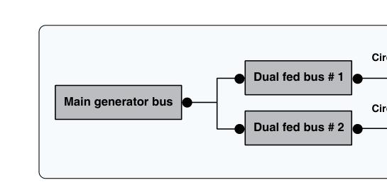
Complex single-engine and light twin aircraft used in commercial operations often employ a dual-bus (or split-bus) electrical architecture. The goal is to maintain power to the most critical instruments and avionics even if one portion of the electrical system fails.
Essential Bus and Main Bus
In a typical dual-bus design, the electrical system is divided into at least two buses:
- Main (primary) bus: Powers the majority of the aircraft's electrical loads — autopilot, non-essential radios, cabin lighting, electric trim, retractable gear motor, and so on. This bus is supplied by the alternator through a main bus tie or bus bar.
- Essential (standby) bus: Powers only the most critical instruments and one communications radio. It can be connected directly to the battery, bypassing the main bus entirely. In the event of a main bus failure (such as a short circuit or bus tie failure), the essential bus remains powered from the battery or from an alternate power path.
Some aircraft add a battery bus that is permanently connected to the battery even when the master switch is off — typically used for the clock and memory functions of avionics. Pilots must be aware that loads left on this bus drain the battery while the aircraft is parked.
Bus Tie and Cross-Tie Systems in Twins
In light twin-engine aircraft, each engine drives its own alternator feeding its own bus. A bus tie relay or switch allows either alternator to supply both buses in the event one alternator fails. During normal operations with both alternators running, the bus tie may be open so that a fault on one bus cannot propagate to the other. On engine failure, the surviving alternator's bus is cross-tied to power essential loads on the failed-engine side.
The specific architecture varies by aircraft make and model, so a commercial pilot transitioning to any new aircraft must study that aircraft's Pilot's Operating Handbook (POH) and Airplane Flight Manual (AFM) electrical system section in detail. The FAA's Airplane Flying Handbook emphasizes that the pilot must understand the specific aircraft's electrical system architecture before operating it, particularly the location and function of every circuit breaker and bus.
Circuit Breakers and Fuses
Each individual circuit is protected by either a circuit breaker or a fuse. Circuit breakers are the dominant protection device on certificated aircraft because they can be reset in flight. A tripped breaker indicates an overcurrent condition — typically caused by a short circuit or equipment malfunction. FAA guidance states that a circuit breaker should not be reset more than once in flight; if it trips again, leave it open. Resetting a breaker into an active short can cause a fire.
Fuses serve the same protective function but must be replaced with an identical-rating spare. Many aircraft carry spare fuses in a holder in the cockpit. Substituting a higher-rated fuse defeats the protection and is strictly prohibited.
Practical Load Management
A commercial pilot must actively manage electrical load, particularly during a partial electrical failure. The technique of load shedding involves turning off all non-essential electrical consumers to stretch battery endurance. A fully charged 24-amp-hour battery powering a 20-amp essential load provides roughly one hour of battery-only operation — but actual capacity is lower in cold temperatures and as the battery ages. The pilot should always calculate the minimum load required to fly the aircraft safely and land at the nearest suitable airport.
Common Test Traps
- Generator vs. alternator charging speed: A common distractor states that generators charge better at low RPM. The opposite is true — alternators produce charging current at idle; older generators required higher RPM to charge.
- Over-voltage vs. under-voltage: The over-voltage protection system disconnects the alternator from the bus to protect avionics; it does NOT reconnect automatically — the pilot must reset it using the ALT half of the master switch per the POH procedure.
- Ammeter direction: On a center-zero ammeter, a left (negative) deflection during cruise means the battery is discharging and the alternator has likely failed — not that the battery is being charged.
- Essential bus during master-off: The battery bus (permanently hot) and the essential bus are sometimes confused. The battery bus remains live with the master off; the essential bus normally requires the battery master to be on unless an alternate feed path is manually selected.
- Circuit breaker reset rule: Reset a tripped breaker only once; if it trips again, leave it open. Resetting repeatedly into a short risks fire — this is a well-tested FAA knowledge test point.